First result on Google 🙄 https://www.amazon.ca/Designing-Power-Supplies-Amplifiers-Second/dp/0956154549
kevin o"conner from London Power writes better , given Kevin is an actual amplifier builder , where as others are not . . . .
Seems Hexfreds are good enough for you, Lynn Olson insisted on dampers and ecdesigns needed to come up with complicated charge transfer supply for his DAC application. Whatever the case, there is little sense for diy people to choose less practical solution for no perceivable difference to himself in his specific system even though it measures or simulates better.Good enough is an ...
Anyone??Although the technical aspects are over my head I've been kinda sorta following this thread to the best of my abilities.
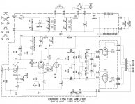
On my current breadboard project I'm using a version of the "cockeyed bridge" that Eli Duttman promoted fairly often here on DIY and also at AA. Part SS and part tube using a 6AX4GTB for slow start.
View attachment 1137519
I'd be interested in any comments about such a design and how it compares to others being discussed.
Also, I've used PSUD for basic voltage predictions but not much beyond that. I'm guessing that it is not able to simulate the design I'm using. Or can it?
What are HEXFREDs? Google tells me its a trademark of Vishay describing a rectifier that is both ultrafast and ultrasoft in recovery. Is Vishay the only supplier of such rectifiers? What other mfg's series are basically the same thing as the Vishay hexfred? To compare pricing and specs.

60hz yes slow, that leaves only the "ultra soft" part that makes them special? Or are they overall better noise-behaved at the zero crossing point because they are both "ultra fast" and "ultra soft"? Vishay terms. Ignoring that they'll rectify at 300khz because they're fast. Why are they better in a tube Amp, does the ultra-soft part behave more like a tube rectifier?
The cockeyed bridge should simulate almost exactly - if you edit the rectifier scheme and choose vacuum tube → full wave.Anyone??
Both of these regimes are full wave rectifier where the peak current meets one vacuum diode; the cockeyed also meets two series UF4007 plain silicon diodes, but that difference is negligible.
Similar performance can also be achieved with a secondary winding without CT (so, half the voltage): just build a normal bridge rectifier for it using UF4007 diodes; and then insert the vacuum diode between the bridge output and the first capacitor.
In both cases, the vacuum diode is just a series element of the peak current loop. It prevents reverse currents during recovery-time of the UF4007s, because its very low value of blocking-capacitance; it also softens the forward current pulses (high perveance of the usual vacuum diodes) and it warms up slowly to prevent crash-starting of the anode supply. In other words all the desirable features of vacuum diodes that minimize noise, and produce a gentle startup.
60hz yes slow, that leaves only the "ultra soft" part that makes them special? Or are they overall better noise-behaved at the zero crossing point because they are both "ultra fast" and "ultra soft"? Vishay terms. Ignoring that they'll rectify at 300khz because they're fast. Why are they better in a tube Amp, does the ultra-soft part behave more like a tube rectifier?
i am sorry but i am not a believer in these rectifiers, i use normal speed rectifiers for 60hz, and if i ever i use those fast rectifiers in my amp is for the simple reason that i have them on hand...
The "fast" or "standard" speed of silicon PN diodes refers to the reverse-conduction behaviour. Silicon PN diodes do not shut off instantly when they are reverse-biased, and the time taken for reverse current to decay varies substantially.60hz yes slow, that leaves only the "ultra soft" part that makes them special?
This is a notable problem when high voltage transformer windings are the source of the input voltage to a rectifier, becuase they have a relatively large leakage inductance. The pulsing nature of the rectifier currents twangs the leakage-inductance, and provokes a nasty-looking noisy waveform as the diodes turn-OFF. Longer recovery-time of PN diodes can aggrovate the noise generated in this way. Also, high-current PN diodes can have very large values of capacitance across the junction at low voltages, storing up enegy which ends up in the undesirable noise.
Search out Mark Johnson's "Quasimodo" thread to learn about tackling the problem in PN diode supplies by snubbing the leakage inductance with a series RC or RC || C network.
OTOH, vacuum diodes have no recovery-time problems, and also have tiny values of capacitance, making them largely immune from any of these problems, and adding a single damper (TV vacuum rectifier) can suffice to suppress problems with PN diodes, as described above. Snubbing is not usually necessary.
Last edited:
Thanks Rod . . . Any comment on the the SS diode portion? Does the SS / tube combo offer any advantage over a tube only design? Are there any downsides to the cockeyed bridge?The cockeyed bridge [has] all the desirable features of vacuum diodes that minimize noise, and produce a gentle startup.
I ask because, although Eli Duttman often recommended it, I rarely see it being used.
Nice idea, but . . .
A rectifier is not exactly a power resistor.
Until a resistor starts smoking, Ohms law is usually "followed" by the resistor.
The current / voltage plot has a constant slope (straight line).
After it warms up, a tube rectifier current / voltage plot is not constant, it forms a curved line.
So what happens when the current varies due to a larger load on B+ as the music volume increases.
The voltage drop across a resistor is proportional to the current.
The voltage drop across the rectifier is not linear versus the current.
Similar, yes.
The same, no.
Just my opinions.
Last edited:
The great advantage of the cockeyed bridge: it offers fullwave rectification with only one vacuum rectifier section. This means that a single damper diode can be used. These are tougher, and lower drop than the usual 5AR4s 5Z4s etc; they often have excellent slow warm up, followed by slow rising ramp of voltage: a great advantage in itself.Thanks Rod . . . Any comment on the the SS diode portion? Does the SS / tube combo offer any advantage over a tube only design? Are there any downsides to the cockeyed bridge?
I ask because, although Eli Duttman often recommended it, I rarely see it being used.
The UF4007 diodes are known-good for the purpose; they see high voltage when reverse-biased, so two or three in series is a good idea. The little caps are an attempt to protect them from transients; these should be rated for 2000V or more.
Short wiring should be used around each diode and to the PT; the ground ends of the UF4007s should terminate near the cap negative.
Overall, it's a good solution, and can be used with confidence, if you have some dampers and a fullwave PT (with CT).
If you have PT without a CT, similar results can be had with a bridge of UF4007s and the damper between the bridge output and the cap's positive.
Nice idea, but . . .
A rectifier is not exactly a power resistor.
Until a resistor starts smoking, Ohms law is usually "followed" by the resistor.
The current / voltage plot has a constant slope (straight line).
After it warms up, a tube rectifier current / voltage plot is not constant, it forms a curved line.
So what happens when the current varies due to a larger load on B+ as the music volume increases.
The voltage drop across a resistor is proportional to the current.
The voltage drop across the rectifier is not linear versus the current.
Similar, yes.
The same, no.
Just my opinions.
agree, the dynamic resistance of the tube rectifier is never linear as in a true resistor and so is the voltage drop...
but one thing for sure, the tube rectifier in my circuit is not converting ac to dc anymore....
incidentally, the GZ34 used in that circuit was able to supply 340mA for a brief spell without breaking a sweat....
in class A, a constant load is seen by the psu, in class AB there is idle psu and full power psu with sag...
in class AB push pull, the goal of the design it to be able to supply power to the full power specs....
Last edited:
i use ez81 , feeding 100uf , 30/40 choke, 100uf.
Even when you're repeating: 100 µF as the first filter capacitor is way beyond the EZ81 ratings that allow for just 50 µF. And what's a 30/40 choke, please?i use an EZ-81 and a pair of SS diodes in full wave , feeding 100uf , 30/40 choke , 100uf.
Best regards!
The arrangement in post #80 has a disadvantage in that the transformer's secondary winding stands at almost B+ above signal ground, so presumably chassis ground, plus the expected AC voltages. It's really unnecessary stress because the same results can be had with its center tap to ground and the diodes transposed into the arms in the classic 5T vacuum valve twin rectifier way.
Best practice for series'ing the semi-con rectifiers is to parallel each with voltage dividing resistors. Need to be mindful of resistor voltage ratings; in that circuit 2W carbon comps would give enough margin, maybe something between 100K and 500K for same tape samples.
All good fortune,
Chris
Best practice for series'ing the semi-con rectifiers is to parallel each with voltage dividing resistors. Need to be mindful of resistor voltage ratings; in that circuit 2W carbon comps would give enough margin, maybe something between 100K and 500K for same tape samples.
All good fortune,
Chris
The voltage stress is not a problem for split-bobbin transformers; and in any case I would expect a new PT to be tested to 2500V in all constructions. Maybe old overwound units are less suitable.
Single section dampers are tougher and better IMHO, and were still fairly widely available last time I looked. 6CJ3s are VERY reliable and give 30s delay, and 30s rise time. So useful! Needing to use only one seems pretty attractive to me.
That's only true if you have stocks of good twin-section vacuum diodes. Modern production seems to remain a fragile and unreliable quantity: bad enough that constructors now routinely put 1N4007s in series with them, to limit the consequential damage from their dramatic failure modes.same results can be had with its center tap to ground and the diodes transposed into the arms in the classic 5T vacuum valve twin rectifier way.
Single section dampers are tougher and better IMHO, and were still fairly widely available last time I looked. 6CJ3s are VERY reliable and give 30s delay, and 30s rise time. So useful! Needing to use only one seems pretty attractive to me.
- Home
- Amplifiers
- Tubes / Valves
- Solid state versus tube rectifiers in a PSU