A B+ secondary for a voltage doubler only needs 1/2 the windings of a center tap full wave secondary.
... or maybe 1/4 ... ? for the same B+ ... ?
Serious Series Circuit:
A transformer secondary sends 350Vrms to a solid state diode anode, diode cathode to a choke, choke out to a capacitor.
350 x 3 = 1050v pk to pk or absolute value of voltage presented to the anode this is the required PIV, two 1N4007;s is good enough...
we see in many designs with ss rectifiers used 3 in series which is even better...
Last edited:
HK's Stu Hegemann was a big fan of low DCR power transformers. In some of his designs he used voltage doubler, which enabled very low secondary DCR, something like 12 Ohms for 330 VDC B+.
a lot of goodies comes with the full wave voltage doublers, and for someone like me designing ang building my own power traffos this is very desirable..
i understand that other people are limited in their choices by what is commercially available, i do not suffer that...
... or maybe 1/4 ... ? for the same B+ ... ?
i use the factor of x2.8, but Patrick Turner used x2.7..
the decision on what secondary voltage to use depends on the size of the power traffo and dcr of the windings...
for me having a bit more voltage is less of an annoyance than having lower voltage when you needed more...
A B+ secondary for a voltage doubler only needs 1/2 the windings of a center tap full wave secondary.
that will be for the hybrid full wave case, 350-0-350 will have an unloaded dc of around 490 vdc into a capacitor input filter, the dynaco st70 had 360-0-360 for a little over 500 volts, when i made my modified power traffo, the secondary was just a single 340vac winding, when rectified into a cap input filter is 470 volts, still a good number....
for a doubler, 470vdc/2.8 = 170vac. so here we see, that winding a 170vac coils is much simpler than winding a 360-0-360 secondary, it is faster and cheaper too since low gage wires are more expensive that heveier gage wires...and the best is insulation requirements are diyer friendly...
True, Drawing copper through a small hole is more expensive than through a bigger hole (small diameter for center tapped full wave windings).
But 2 times the copper weight is expensive too (to run either a full wave bridge rectifier, or a full wave voltage doubler.
Have you checked the price of copper lately?
1/2 the turns, 1/4 the turns, the issue is I-squared x R.
Length times cross section area dictates R.
The integral of I depends on the input filter type, full wave center tap, bridge, or voltage doubler.
Power supply design has tradeoffs, and those tradeoffs change with time as other conditions come along.
And no, I am not going to try to save the planet by using switching supplies for my vacuum tube amplifiers.
Last edited:
less expensive to buy a gage #20 than say #32. two to three years ago, price of copper magnet wires in Manila was only 300 pesos($6) yet today it is 1000+ pesos ($20) per kilogram....all the more reason to go full wave bridge...
Tony - the issue here is inductive kick from input choke, which is in series with rectifier. It could be something like 10× the AC voltage. It occurs only on start-up, a single spike. You can see it in PSUD2.350 x 3 = 1050v pk to pk or absolute value of voltage presented to the anode this is the required PIV, two 1N4007;s is good enough...
we see in many designs with ss rectifiers used 3 in series which is even better...
I wonder if this model is complete enough. At turn-on, everything down-stream of the input inductor is pretty much approximately a dead short in that time frame. This is actually a separate issue for crazy wacko folk doing 866A rectifiers, which need both to be heated to their boiling point, and then also cannot exceed their peak current during turn-on through B+ approaching full on. Another time delay, shocking.
But even in the worst-case of semi-con rectifiers immediately conducting into a series inductor and from a low impedance source, the rectifiers see that inductor in series with a small and lossy impedance. The historical observation that "nobody died here" makes me think that our computer models are incomplete for non-static conditions.
Of course, things will change as models improve. We'll ultimately discover that we're ourselves only models, and the real question will become that of What Generation of modeled reality are we? The possibility that we are the first generation is impossibly small. Sweet dreams, fellow Neo's.
But that's progress, Party on,
Chris
Tony - the issue here is inductive kick from input choke, which is in series with rectifier. It could be something like 10× the AC voltage. It occurs only on start-up, a single spike. You can see it in PSUD2.
sorry, i do not put too much faith in PSUD2....so how long is the spike? one cycle? 1/60 secs?
this is why i will always choose ss rectifiers with high current capacity, its thermal mass can absorb more heat...

Some have missed my point:
An output tube that has a logarithmic increasing current from cold to fully warmed up is very different than . . .
PSUD 2-step Load.
Why does PSUD bother to draw a B+ voltage curve versus time, when the load versus time of its 2 steps, is not at all like the load curve of a real indirect heated output tube.
I think many of the questions dealt with in this thread can be answered with:
'Designing Power Supplies for Tube Amplifiers', 2nd Edition, by Merlin Blencowe.
The book helped separate the myths from the facts for me
'Designing Power Supplies for Tube Amplifiers', 2nd Edition, by Merlin Blencowe.
The book helped separate the myths from the facts for me
Some have missed my point:
An output tube that has a logarithmic increasing current from cold to fully warmed up is very different than . . .
PSUD 2-step Load.
Why does PSUD bother to draw a B+ voltage curve versus time, when the load versus time of its 2 steps, is not at all like the load curve of a real indirect heated output tube.
For the most part the stepped load is good enough. What new information would be revealed with a new non linear startup curve? If someone really wanted to bother you could do it in spice. I recall seeing tube models with warmup characteristics.
Just saying, a simulation, with voltage/ time curves is just a simulation.
It is not necessary a correct curve, but many trust in it.
Bob Pease, Pease Porridge, had at least one comment about simulation.
Good enough is an old government worker statement.
The original Tacoma Narrows bridge was good enough, until the 15 MPH wind came along.
It is not necessary a correct curve, but many trust in it.
Bob Pease, Pease Porridge, had at least one comment about simulation.
Good enough is an old government worker statement.
The original Tacoma Narrows bridge was good enough, until the 15 MPH wind came along.
Some have missed my point:
An output tube that has a logarithmic increasing current from cold to fully warmed up is very different than . . .
PSUD 2-step Load.
Why does PSUD bother to draw a B+ voltage curve versus time, when the load versus time of its 2 steps, is not at all like the load curve of a real indirect heated output tube.
actually in any tube amps, there are two steps the filament heating up and the B+ coming up, filaments need at least 11 seconds to fully warm up, meanwhile the B+ rises to maximum level that it can achieve, then as the tubes start to draw currents, this B+ whilst at maximum starts to drop to the operating level.....
now i dare PSU2 to capture these.....
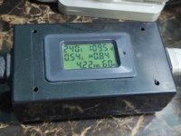
how do i know? I use a power monitoring device better than the kill-a-wat...with this i am able to observe the power as it is being drawn the the slowing ramping up of power draw righ after the filaments have warmed up and as the power tubes draw plate power....
Attachments
Please can you elaborate? I can't find the book online. If you could summarise your findings, that would be much appreciated.I think many of the questions dealt with in this thread can be answered with:
'Designing Power Supplies for Tube Amplifiers', 2nd Edition, by Merlin Blencowe.
The book helped separate the myths from the facts for me
the author is a member and a poster here in our forum, MerlinB....
- Home
- Amplifiers
- Tubes / Valves
- Solid state versus tube rectifiers in a PSU