Assembly has at last began.
I'll be fitting the CL90 once wiring begins.
I'm a bit hesitant to mount the PCB and wire everything as a precaution.
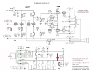
Resistors R112, 212, 116 & 216 are presently 270Ω, so i'll be changing them to 300Ω and take things from there.
I'll be fitting the CL90 once wiring begins.
I'm a bit hesitant to mount the PCB and wire everything as a precaution.
Resistors R112, 212, 116 & 216 are presently 270Ω, so i'll be changing them to 300Ω and take things from there.
Attachments


Does it require an elevated heater supply for the splitter? 12AT7 is rated only 90V of heater-cathode voltage
Calpe,
Are you thinking of firing it up before mounting in the chassis? Probably safer to do it rather than have things floating about. Be sure to connect the power inlet ground terminal to the chassis. Use the light bulb limiter trick if you are hesitant. It has to be a conventional bulb, NOT a LED or compact fluorescent.
S.
Heater elevation on the board?The SPP has heater elevation on the board.
Yes.Heater elevation on the board?
R2 & R3 (bypassed by C3) are set as a voltage divider & that provides the heater elevation in this circuit.
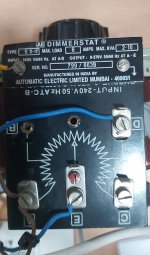
Steve, i dug our an old variac, damn thing wasn't working. It appeared the brush on the rotary slider had worn away, thus no output from the slider A.C. output. I rotated the brush and obtained an output and i'm sure it'll work for the tests. I'll need to look for a brush from somewhere.Calpe,
Are you thinking of firing it up before mounting in the chassis? Probably safer to do it rather than have things floating about. Be sure to connect the power inlet ground terminal to the chassis. Use the light bulb limiter trick if you are hesitant. It has to be a conventional bulb, NOT a LED or compact fluorescent.
S.
I checked the mains A.C. today with a Fluke i have, sadly it wasn't 240. I'll be contacting the Electricity board here to report the fact that i had nearly 248/249!
All the transformers are now all mounted.
Rear panel has all the needed items i wanted to fit.
Mains socket, mains switch, chassis mounted fuse holder, all to the rear right (looking from the back).
Speaker posts for 4, 8 and 16 ohms (my choice), mounted on the rear left.
Front panel i have left and right audio input sockets and a volume control.
I took note from Skunkie Designs as she stated if placing a 100K Vol. pot. then resistor R100 could be changed from 220K up to 1M, which i'v now done.
As mentioned resisitors R112/212 R116/216 are now 300R.
I'll probably choose to 'fire up' with the PCB not fitted to the top plate.
Just need to sort out all the wonderful coloured cables and to what PCB connections they go to😕
New term for me 'heater elevation'Yes.
R2 & R3 (bypassed by C3) are set as a voltage divider & that provides the heater elevation in this circuit.
I had the same problem with my old variac. Too bad, I could have had 3 or for the same price (free).
Mains AC often runs over the nominal. I really encourage you to install the amp in the chassis before starting it up. Much safer and you can get the grounds sorted out too. Without the grounds sorted you might get hum that is a result of improper grounding that shouldn't occur in the chassis. The ground side of your input jacks are insulated from the chassis, correct?
S.
S.
I'll do that Steve, otherwise i'm going to have cables all over the place.Mains AC often runs over the nominal. I really encourage you to install the amp in the chassis before starting it up. Much safer and you can get the grounds sorted out too. Without the grounds sorted you might get hum that is a result of improper grounding that shouldn't occur in the chassis. The ground side of your input jacks are insulated from the chassis, correct?
S.
Input sockets isolated?
Ground - Earth.....😕 ?
I always get confused between these two.
Earth (U.K.) is the green/yellow cable.
So the metal chassis has to be connected to Earth (green/yellow).
The symbols of Earth and Ground would be?
I did:
Brown - This is the live wire (in older installations it may be red).
Green & Yellow - This is the earth wire (in older installations it may be green).
Blue, Brown, and Green & Yellow.
Answered by Dave, Electrical Safety Expert
Blue - This is the neutral wire (in older installations it may be black).Brown - This is the live wire (in older installations it may be red).
Green & Yellow - This is the earth wire (in older installations it may be green).
http://www.valvewizard.co.uk/heater.htmlNew term for me 'heater elevation'
fairly concise explanation there.
As per Post 292The colours in North America are different. Suggest you google it for your area.
S.
Definitely - Blue is neutral. Brown is live and Green/Yellow is earthI did:
Blue, Brown, and Green & Yellow.
Answered by Dave, Electrical Safety Expert
Blue - This is the neutral wire (in older installations it may be black).
Brown - This is the live wire (in older installations it may be red).
Green & Yellow - This is the earth wire (in older installations it may be green).
I'll have to double check the input RCA sockets. Can anyone recommend a type?Much safer and you can get the grounds sorted out too. Without the grounds sorted you might get hum that is a result of improper grounding that shouldn't occur in the chassis. The ground side of your input jacks are insulated from the chassis, correct?
S.
It's a thought the question of ground/s & earth.
Both of which are not the same.
We know that the metal chassis must be connected to earth.
Sometimes the trickiest bit, as far as minimizing hum is concerned, is connecting the amplifier (read circuit) ground to the earth ground. The earth ground being the earth lead on the AC line cord that is also connected directly to your chassis. You only want to do this at one point hence the need for insulated RCA jacks. My SPP builds worked fine when I connected the circuit ground on the board at the inputs to the chassis earth. The green lead in the picture below.

RCAs: Something like this perhaps?

RCAs: Something like this perhaps?
As per today, slowly does it..... trying to fit all other home matters in too.
Pictures speak for themselves/
Variac, now with a temp fixed on the wiper brush.
I wonder from where i could obtain a new or suitable brush?
Chassis putting it together.
Screws joints i'm having to remove in hidden areas the black covering so there is continuity throughout the case.
Phono input sockets replaced with chassis isolated types.
There's so many bits and bobs to check.
Final task is to work out where all the cables correctly go.
Attachments


- Home
- Amplifiers
- Tubes / Valves
- Tubelab SPP first timer build