
Ok so the "bycicle bulb"...The lower the power, the larger its sensitivity, but easier to burn. 6.3V 50mA may be.
Just to confirm if it's ok... I built essentialy the same thing that is on the schematic that you sent me first... the oscillator, only difference is that I had already wired pin 7 -pentode's cathode to gnd.
For trimmer before the crystal I had used small plastic gang from newer radio... I had seen some people using those on similar projects. Should be good right? What value capacitor I could use instead of trimmer if I will need to be troubleshooting?
Right now I get -5v (negative) on triode's screen, is this ok?
Perfect. As the grid goes negative is because it is oscillating. This is a good proof.
The gang may work. Take into account that may be a point near the minimum capacitance the oscillator may stop as too low C decouples the crystal fom the triode. Try also to make wiring shorter.
Could you listen the (clean) signal in a receiver?
The gang may work. Take into account that may be a point near the minimum capacitance the oscillator may stop as too low C decouples the crystal fom the triode. Try also to make wiring shorter.
Could you listen the (clean) signal in a receiver?
I'm glad to hear that.Perfect. As the grid goes negative is because it is oscillating. This is a good proof.
The gang may work. Take into account that may be a point near the minimum capacitance the oscillator may stop as too low C decouples the crystal fom the triode. Try also to make wiring shorter.
Could you listen the (clean) signal in a receiver?
Ok, I am at work and I had just bought the crystal on the way here. So I will try with 6mhz when I get home. I hope that I will be able to hear the difference as stations bellow around 6.5mhz were quiet already yesterday when I was listening with oscillator off, I hope that I will be able to hear the difference, any artefacts in noise or something. Maybee this is because I had just used short wire for the antenna. I must make the antenna for the radio, but I figured a piece of wire should be enough for now as I have my oscillator close...
Wiring for the gang or also from power supply for b+ & heater?Try also to make wiring shorter.
Also what would be the approximate "allowed" min - max value of crystal decoupling capacitor-trimmer?
Last edited:
Mainly all RF live paths: grid to Xtal, Xtal to variable, variable to gnd, cathode, and the capacitive divider. There isn't a minimum, here too the shorter, the better.Wiring for the gang or also from power supply for b+ & heater?
Also what would be the approximate "allowed" min - max value of crystal decoupling capacitor-trimmer?
The tube surelly will put a loud signal into any closer receiver. You will be able to listen a powerful clear signal, perhaps with a small modulation by the line frequency. But in any case it will be easy to identify. Again, at the Xtal frequency and the harmonics (entire multiple of the Xtal frequency).
Keep in mind that Xtals has two main frequencies of operation: the series resonance and the parallel. Both are relatively close (few KHz appart) and will vary another few KHz with the trimmer. And Xtals are labelled acording to certain external capacitance, between 20 and 30pF. Because of all those facts, scan the receiver some KHz above and below Xtal frequency.
Ok, thank you.Mainly all RF live paths: grid to Xtal, Xtal to variable, variable to gnd, cathode, and the capacitive divider. There isn't a minimum, here too the shorter, the better.
The tube surelly will put a loud signal into any closer receiver. You will be able to listen a powerful clear signal, perhaps with a small modulation by the line frequency. But in any case it will be easy to identify. Again, at the Xtal frequency and the harmonics (entire multiple of the Xtal frequency).
Keep in mind that Xtals has two main frequencies of operation: the series resonance and the parallel. Both are relatively close (few KHz appart) and will vary another few KHz with the trimmer. And Xtals are labelled acording to certain external capacitance, between 20 and 30pF. Because of all those facts, scan the receiver some KHz above and below Xtal frequency.
Will shorten those paths and will report back when I get home about the results with new crystal.
I need to make a comment. The above depicted Hertx loop or Hertz ring works where some levels of RF are present. This isn't the case of an Xtal oscillator. You surely will note it placing it close to the choke. Choke current RF is very low, so it will not do rhe buld to light up.
Thinking that you can build it using one of those old small lamps for Xmas tree.
Thinking that you can build it using one of those old small lamps for Xmas tree.
Ok, thank you for clarification. I think that I have some old xmas lights somewhere, also some 6v bulbs from old car radios. Will give it a try.I need to make a comment. The above depicted Hertx loop or Hertz ring works where some levels of RF are present. This isn't the case of an Xtal oscillator. You surely will note it placing it close to the choke. Choke current RF is very low, so it will not do rhe buld to light up.
Thinking that you can build it using one of those old small lamps for Xmas tree.
Oh man, it works!!!! @6mhz, I do need to have receiver on full volume, because that frequency is silent any way, but it works. I didn't shorten the wiring or dropped the voltage yet, I had just changed the crystal. Give me a minute to upload a video.
Thank youCongratulations. Welcome to the RF world
I was never so happy to hear the silence.
I will call it good for a day because I feel a bit tyred and I start to be absent when working on something and such voltage is no place to be absent... But tommorow I will solve the remaining stuff and make the hertz loop ... everything should be straight forward, will report when I'm there because it will be time to do the final tank coil I believe...?
Bipolar capacitor that goes in parallel with the screen dropping resistor of the pentode must be 400v? Just in case I grabbed 10uF 100v, because that was the highest they had at the store, but it's way too low I reckon?
Perhaps may be. Don't buy foolery from audio grade capacitor. Any motor running cap may be. Use a value that you have at hand. Keep in mind this isn't a proffesional quality device.
Mooving the trimmer in series may enable you to change slightly the frequency. But possibly the SW receiver lacks sufficient selectivity to show you the change.
Mooving the trimmer in series may enable you to change slightly the frequency. But possibly the SW receiver lacks sufficient selectivity to show you the change.
Prior to start building the final stage (pentode section) it is important to have at hand a milli or micro ammeter. A direct device capable of 25 to 50mA suffices. If you lack such a range, it may be any microammeter properly shunted. Measure the full scale range and the coil resistance. Thus you need to make a shunt to be wired in parallel to the ammeter to take an idea of the current drawed by the final stage. Again, any analog moving coil will do. The final stage current will produce a large dip (a minimum) when the tank is adjusted to resonance with the signal at its grid or at an harmonic. This point of minimum is important because two reasons: the amplifier is safely managing the signal and giving the most from it. Once the minimum is found, the amplifier is tuned to resonance and is capable of delivering power to a load.
When our load (in this case will be the Hertz loop), the current must increase again. Thus you need to retune again
This procces is iterative three or four times. You then will be ready to build the audio section for amplitude modulation.
There are literature on the net and books about building a shunt. This is one. If you can't find one, let me know.
Last edited:
Ok, I had just finished the modifications, wires are shortened, plate voltage is 160v (50k resistor used) and I had split the two pies of coil & cut the bobbine.Prior to start building the final stage (pentode section) it is important to have at hand a milli or micro ammeter. A direct device capable of 25 to 50mA suffices. If you lack such a range, it may be any microammeter properly shunted. Measure the full scale range and the coil resistance. Thus you need to make a shunt to be wired in parallel to the ammeter to take an idea of the current drawed by the final stage. Again, any analog moving coil will do. The final stage current will produce a large dip (a minimum) when the tank is adjusted to resonance with the signal at its grid or at an harmonic. This point of minimum is important because two reasons: the amplifier is safely managing the signal and giving the most from it. Once the minimum is found, the amplifier is tuned to resonance and is capable of delivering power to a load.
When our load (in this case will be the Hertz loop), the current must increase again. Thus you need to retune again
This procces is iterative three or four times. You then will be ready to build the audio section for amplitude modulation.
There are literature on the net and books about building a shunt. This is one. If you can't find one, let me know.

Noise got more silent as I dropped the plate voltages, I didn't notice any other changes.
I must go now, but as I come back I will process what you had written in last post and go from there.
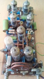
Okay. Looks pretty good. Glad to know you are enjoying. One only objection: remove the metallic piece inside the choke. It acts partially as a shorted turn absorving energy from the choke. That's not good. Use a plastic, wood or ceramic one.
Next time let me know if the pentode's grid biasing resistor and capacitor (100pF & 100K) are placed in site. If the case, say us which is the voltage appearing at the grid side (negative to the grid pin). If it is below 15 or 20V, thus we will need to change the capacitor divider across grid, cathode and ground in order to increase slightly the current to the crystal and increase the excitation for the pentode.
Don't worry about time. This is a hobbie and we had much other things to do; and some of them are more important to us.
Also let us know if the receiver is capable of listen FM in the frequencies you are listening to the Xtal oscillation. We can give a try to the xCH81 to make a small FM transmitter.
Good. The "mount" for the choke is actually plastic. I was thinking about that. This is just the prototype for easyer trial and error, when I get whole project together I will find housing for it... Finished circuit will also be point to point.Okay. Looks pretty good. Glad to know you are enjoying. One only objection: remove the metallic piece inside the choke. It acts partially as a shorted turn absorving energy from the choke. That's not good. Use a plastic, wood or ceramic one.
Next time let me know if the pentode's grid biasing resistor and capacitor (100pF & 100K) are placed in site. If the case, say us which is the voltage appearing at the grid side (negative to the grid pin). If it is below 15 or 20V, thus we will need to change the capacitor divider across grid, cathode and ground in order to increase slightly the current to the crystal and increase the excitation for the pentode.
Don't worry about time. This is a hobbie and we had much other things to do; and some of them are more important to us.
Also let us know if the receiver is capable of listen FM in the frequencies you are listening to the Xtal oscillation. We can give a try to the xCH81 to make a small FM transmitter.
Amp meter solved 🙂 old VU meter with 2.2ohm shunt resistor.

I'm a bit lost about pentode's grid biasing resistor, is it R3 and capacitor is C5? If that is the case is 200pF good for the C5?
Those two are not in site yet, just let me know if I should use 100pF instead and I will add both components and report.

I tend to always rush myself, but when working on such things I am braking myself down not to rush in a danger...
Yep, I wish that I could be 100% in the project, but then there comes the everyday responsibilities...
My receiver covers FM 88-107mhz.
- Home
- Amplifiers
- Tubes / Valves
- Help me put these tubes into good use... I need a project