Should I try with 10pf? Or maybee 10pf in series with the gang?✅ ☑️
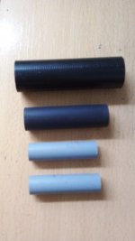
Also let us know if you can measure the large gang capacitance (the bigger one in the radio) and if you have a piece of plastic tube say 2cm diameter and 2cm height to start building plate tank circuit. For this we will need about 1 metre of copper wire preferably enameled of 0.4 to 0.7mm diameter.

-2v with 27pF across the choke...Not still. 10pF may be too low. Try also a 22/33 pF across the choke.
Only device that I have for capacitance measurement is DMM, range up to 2uF... will try and see what I get. Will look for the wire and tube... oh and I got the bypolar 10uF capAlso let us know if you can measure the large gang capacitance (the bigger one in the radio) and if you have a piece of plastic tube say 2cm diameter and 2cm height to start building plate tank circuit. For this we will need about 1 metre of copper wire preferably enameled of 0.4 to 0.7mm diameter.
I cant measure it, my DMM wont go that low.Only device that I have for capacitance measurement is DMM, range up to 2uF... will try and see what I get. Will look for the wire and tube... oh and I got the bypolar 10uF cap
Don't worry. In any case the gang must be in the order of 400 to 500pF closed.
When you get the bobbin for the plate tank, verify at eye that it hasn't any metallic part inside it. If ot looks ok, place the piece of plastic in a microwave oven during 3 o 4 seconds. Thus open the door and check if its temperature rose notoriously, it means that is highly loose for RF and discard it. Those piece of tubing from fax or electronic cash registers go OK for the task. If several of them are at hand, catch those in the 2 ~ 3 cm diameter.
When you get the bobbin for the plate tank, verify at eye that it hasn't any metallic part inside it. If ot looks ok, place the piece of plastic in a microwave oven during 3 o 4 seconds. Thus open the door and check if its temperature rose notoriously, it means that is highly loose for RF and discard it. Those piece of tubing from fax or electronic cash registers go OK for the task. If several of them are at hand, catch those in the 2 ~ 3 cm diameter.
Attachments
Returned 100pF and had tryed 27pF in series with the gang, voltage is -2,88vThus return to the 100pF unit.
Ok, reverted to original.Ok. Leave the gang alone betwee crystal return and ground to return to the -3V original.
A crystal oscillator can also be used for narrow band FM, when designed for it. Such a circuit goes under the name VCXO. For instance, a standard CB Xtal (~9 MHZ fundamental) can be pulled about 20 KHz (enough to make a 99 MHz FM transmitter as linearity can be approved via frequency feedback). https://ecsxtal.com/what-is-a-vcxo-voltage-controlled-crystal-oscillator.The project at post #102 formally uses phase modulation. Try to frequency modulate a Xtal results in phase modulation.
But by the moment forget it. First, enjoy the AM TX.
It's like that: Band is clear around 6mhz anyway. When I turn on the oscillator I can hear some noise a bit above the 6mhz. That noise goes away if I change the gang position. If I measure pentode's grid, noise become much louder as long as I am making connection with DMM and more silent if I try to measure the pentode's screen.Okay. Is the clear signal still on the receiver?
Good to know, but one thing at a time.A crystal oscillator can also be used for narrow band FM, when designed for it. Such a circuit goes under the name VCXO. For instance, a standard CB Xtal (~9 MHZ fundamental) can be pulled about 20 KHz (enough to make a 99 MHz FM transmitter as linearity can be approved via frequency feedback). https://ecsxtal.com/what-is-a-vcxo-voltage-controlled-crystal-oscillator.
Okay. Thus its all by now. When you have at hand the elements to build the tank, we will continue. You are my hands at this moment.
Eventually you can try the audio channel. If you want, start with it. But leave pentode plate and screen unpowered too. So we will have both triodes ready but both pentodes iddle.
Eventually you can try the audio channel. If you want, start with it. But leave pentode plate and screen unpowered too. So we will have both triodes ready but both pentodes iddle.
Yeah. But I believe that for good sound modulating a Xtal with reactance and listening in a regular FM RX, it is needed to pass the audio signal by a severe low pass filter in order to increase the low frequencies respect to the high because in the equation for PM is a derivative with respect to frequency thus high notes modulate the Xtal much more than lower if I am remembering well.A crystal oscillator can also be used for narrow band FM, when designed for it. Such a circuit goes under the name VCXO. For instance, a standard CB Xtal (~9 MHZ fundamental) can be pulled about 20 KHz (enough to make a 99 MHz FM transmitter as linearity can be approved via frequency feedback). https://ecsxtal.com/what-is-a-vcxo-voltage-controlled-crystal-oscillator.
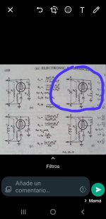
The project at post #102 uses a pentode ECL84 as reactance modulator and the triode as the Xtal oscillator (note for readers: Xtal is an acronym for Crystal in RF jergon). There are two Xtals about some KHz apart in the 16MHz fundamental range, selectable with a common switch. The "reactor pentode" has a choke in the screen supply and a resistance to plate, both live for RF. The audio is injected from a walkman earphone used as dynamic mike in a preamplifier EF184. Thus the ECL84 is a capacitance multiplier driven by the audio signal. Them, 2 steps of EL84 each tripling freq. and the final is a push pull EL84. A EM84 indicator serves to adjust all the stages measuring the voltage rectified at the grids, critically coupled to the previous stage and plate and grids all series feed. The Frankestein gives about 4W into +/- 150Mhz with 240VDC @ 50 ohm. Observe all tubes was from TV and all has the x84 in the part number, so l called it "The 84 transmitter".
I could listen a clean signal in my FT7800 rig, and depending on the volume of the receiver, all things start to oscillate because not only in Larsen Effect but in the mechanical vibration of the Tx because all was in the same workbench.
Attachments
I'm looking for wire & bobbin right now and will build the tank first... Only question I have for the audio section is what kind of audio choke would I need. It's best that I try to get it ASAP, because probably I will need to get it ordered and might aswell order sooner than wait for it later.Okay. Thus its all by now. When you have at hand the elements to build the tank, we will continue. You are my hands at this moment.
Eventually you can try the audio channel. If you want, start with it. But leave pentode plate and screen unpowered too. So we will have both triodes ready but both pentodes iddle.
- Home
- Amplifiers
- Tubes / Valves
- Help me put these tubes into good use... I need a project