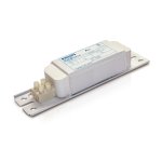
Would it be worth to get audio output transformer over ballast? I can get ballast for less than 10eur and localy...As audio choke you may use the primary of an audio output transformer, or an electromagnetic ballast for fluorescent lamps, 10 to 40 W. Not electronic ballast!
Audio transformer on the other hand... we know the prices 🙂

Regarding the plate tank, one option is to make one with some similtude to this:
https://www.diyaudio.com/community/threads/a-new-fm-tuner-with-compactron-tubes.382570/page-6 post 116 and following.
It isn't good to be self referential here, so if you find another idea or have your own, still better.
https://www.diyaudio.com/community/threads/a-new-fm-tuner-with-compactron-tubes.382570/page-6 post 116 and following.
It isn't good to be self referential here, so if you find another idea or have your own, still better.
FM broadcasting uses preemphasis at the transmitter and deemphasis at the receiver, most countries using 50 uS and in a way not to exceed 75 Khz deviation. So when using a 9 MHz VCXO, deviation has to be 7.5 KHz.Yeah. But I believe that for good sound modulating a Xtal with reactance and listening in a regular FM RX, it is needed to pass the audio signal by a severe low pass filter in order to increase the low frequencies respect to the high because in the equation for PM is a derivative with respect to frequency thus high notes modulate the Xtal much more than lower if I am remembering well.
The project at post #102 uses a pentode ECL84 as reactance modulator and the triode as the Xtal oscillator (note for readers: Xtal is an acronym for Crystal in RF jergon). There are two Xtals about some KHz apart in the 16MHz fundamental range, selectable with a common switch. The "reactor pentode" has a choke in the screen supply and a resistance to plate, both live for RF. The audio is injected from a walkman earphone used as dynamic mike in a preamplifier EF184. Thus the ECL84 is a capacitance multiplier driven by the audio signal. Them, 2 steps of EL84 each tripling freq. and the final is a push pull EL84. A EM84 indicator serves to adjust all the stages measuring the voltage rectified at the grids, critically coupled to the previous stage and plate and grids all series feed. The Frankestein gives about 4W into +/- 150Mhz with 240VDC @ 50 ohm. Observe all tubes was from TV and all has the x84 in the part number, so l called it "The 84 transmitter".
I could listen a clean signal in my FT7800 rig, and depending on the volume of the receiver, all things start to oscillate because not only in Larsen Effect but in the mechanical vibration of the Tx because all was in the same workbench.
Long ago phase modulation was used to produce FM (without reactance modulator), fairly complex by adding a double sideband suppressed carrier signal to the 90 deg phase shifted carrier. The resulting signal was fed to a chain of frequency multipliers plus a mixer to a lower frequency, followed by another set of frequency multipliers to the final frequency. The PM was converted to FM with an integrator for the audio signal.
Ok, will check this out.Regarding the plate tank, one option is to make one with some similtude to this:
https://www.diyaudio.com/community/threads/a-new-fm-tuner-with-compactron-tubes.382570/page-6 post 116 and following.
It isn't good to be self referential here, so if you find another idea or have your own, still better.
What should be the electrolityc capacitors voltage for audio section?
Also what value resistors should be used for pentode's cathode towads the ground (parallel with 100uF cap) and at the input (parallel with 100pF cap)?
If I remember properly, it's the Armstrong's method.FM broadcasting uses preemphasis at the transmitter and deemphasis at the receiver, most countries using 50 uS and in a way not to exceed 75 Khz deviation. So when using a 9 MHz VCXO, deviation has to be 7.5 KHz.
Long ago phase modulation was used to produce FM (without reactance modulator), fairly complex by adding a double sideband suppressed carrier signal to the 90 deg phase shifted carrier. The resulting signal was fed to a chain of frequency multipliers plus a mixer to a lower frequency, followed by another set of frequency multipliers to the final frequency. The PM was converted to FM with an integrator for the audio signal.
Ok, will check this out.
What should be the electrolityc capacitors voltage for audio section?
100uF suffices because no need for hifi here. But if you have at hand 220 or 47 use them.
About 330 to 470R @1W.Also what value resistors should be used for pentode's cathode towads the ground (parallel with 100uF cap) and at the input (parallel with 100pF cap)?
Thank you, but I was thinking of capacitors voltage ratings.100uF suffices because no need for hifi here. But if you have at hand 220 or 47 use them.
About 330 to 470R @1W.
Thank you. Except for pentode's grid, this would be at least 300v as it goes from B+ to ground, right?Ok. For cathodes, 25V. xCL85 triode will have 2 or 3DCV and pentode about 15~17V.
Yes.Thank you. Except for pentode's grid, this would be at least 300v as it goes from B+ to ground, right?
I was thinking about increasing the oscillator's efficiency in order to get a bigger excitation for the pentode final stage. You may try anorher oscillator topology. Do you want?
These are.
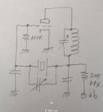
What is called a gimmick is a hombrewed variable capacitor made with two insulated wires whose dielectric is the cable plastic. No more than 5 or 6pF are needed and about 5cm of a twisted pair of cables may go; such those inside cat 5 utp. This is an old trick used for neutralizing amplifiers in tube low power or QRP transmitters. The coil is also a tank and will requiere some experimentation, and we no longuer needed the choke.
The second is also an option several times used by me. In fact the 150MHz already depicted after, uses this kind of oscillator.
Choose the one you like and talk obout component values.
These are.
What is called a gimmick is a hombrewed variable capacitor made with two insulated wires whose dielectric is the cable plastic. No more than 5 or 6pF are needed and about 5cm of a twisted pair of cables may go; such those inside cat 5 utp. This is an old trick used for neutralizing amplifiers in tube low power or QRP transmitters. The coil is also a tank and will requiere some experimentation, and we no longuer needed the choke.
The second is also an option several times used by me. In fact the 150MHz already depicted after, uses this kind of oscillator.
Choose the one you like and talk obout component values.
Attachments

Last edited:
Yes, I would like to. Sounds good.I was thinking about increasing the oscillator's efficiency in order to get a bigger excitation for the pentode final stage. You may try anorher oscillator topology. Do you want?
This is.
What is called a gimmick is a hombrewed variable capacitor made with two insulated wires whose dielectric is the cable plastic. No more than 5 or 6pF are needed and about 5cm of a twisted pair of cables may go; such those inside cat 5 utp. This is an old trick used for neutralizing amplifiers in tube low power or QRP transmitters. The coil is also a tank and will requiere some experimentation, and we no longuer needed the choke.
Nice. Had a quick look now, but I'm in a rush and will study last few posts later. I got the 0.6mm enamel wire, pcv bobbine and other components for audio section. I'm heading back to city now to get the ballast."Gimmick" datum: http://sm0vpo.altervista.org/begin/gimmik-0.htm
Honesty, I don't know wich one too choose. Are there any benefits with one over the other? I would like to put that 0.6mm laquer wire that I bought and would there be any "special" components such as more chokes that I would need to get for one or the other, except for caps and resistors?I was thinking about increasing the oscillator's efficiency in order to get a bigger excitation for the pentode final stage. You may try anorher oscillator topology. Do you want?
These are.
What is called a gimmick is a hombrewed variable capacitor made with two insulated wires whose dielectric is the cable plastic. No more than 5 or 6pF are needed and about 5cm of a twisted pair of cables may go; such those inside cat 5 utp. This is an old trick used for neutralizing amplifiers in tube low power or QRP transmitters. The coil is also a tank and will requiere some experimentation, and we no longuer needed the choke.
The second is also an option several times used by me. In fact the 150MHz already depicted after, uses this kind of oscillator.
Choose the one you like and talk obout component values.
Ok, I would like to go with the second circuit then.Usually the second circuit (the one with the cathode grounded) gives best results.
No, having the "audio choke", the milliammeter and the bobbins for the tanks, no more need for rare materials. That's all.

I hope that this is the right ballast. It's the only one that I could find and the last one in stock.
- Home
- Amplifiers
- Tubes / Valves
- Help me put these tubes into good use... I need a project