Hmm 🙂 That should be plenty fast enough Jan. Perhaps you are just working on circuits that take a lot of converging to set the operating points.
Yes I thought so too.
The operating point is quickly found, but then the whole analysis proceeds rather slow.
Maybe there's something in my PC that hogs CPU time.
Edit: CPU use peaks at 90% when running the sim ...
Jan
The operating point is quickly found, but then the whole analysis proceeds rather slow.
Maybe there's something in my PC that hogs CPU time.
Edit: CPU use peaks at 90% when running the sim ...
Jan
Hard to say. We need a 'standard' sort of test to run to see how things compare to others.
Most of mine seem to run in seconds although I have had some that can take a while such as outputting a .wav file from a sim.
Even quite complex ones like this run in well under 2 seconds and the CPU wasn't very high.


Most of mine seem to run in seconds although I have had some that can take a while such as outputting a .wav file from a sim.
Even quite complex ones like this run in well under 2 seconds and the CPU wasn't very high.
I have a couple of amp designs in sim, they are similar in topology and performance, the Wolverine and the BC-1. BC-1 takes much longer to run ~8s vs 40s the transient, I am trying to figure out why, what exactly in the circuit is causing it. I have found that if I get a design into instability, it oscillates, it takes a lot longer.
Post your design 🙂 just kidding, it might be proprietary, I'll post mine 🙂 even the Wolverine V4 that seems to be proprietary now 🙂
Post your design 🙂 just kidding, it might be proprietary, I'll post mine 🙂 even the Wolverine V4 that seems to be proprietary now 🙂

Yes, I see, orders of magnitude more iterations.
Do you set the timestep or let LTspice figure it out?
Jan
Do you set the timestep or let LTspice figure it out?
Jan

Well that's good, you figured out what my problem is,
.options maxstep, now onto recall/figure out what that's for 🙂
.OPTIONS -- Set simulator options
iirc it was in Bob's book suggesting to use a different number for a different thd measurment freq?
Its in the BC-1 sim he gave me a while ago.
Thanks
.options maxstep, now onto recall/figure out what that's for 🙂
.OPTIONS -- Set simulator options
| Maximum step size for transient analysis |
Its in the BC-1 sim he gave me a while ago.
Thanks
I think in my case it is the min step size that is so small that it needs a huge number of steps thus runs very slow.
The step size is set by LTspice depending on how fast voltages and currents change from step to step. So a circuit with quickly varying values gets a small timestep assigned.
With slow circuits, LTspice may use a timestep that is so large that details get lost, so it makes sense to set a maxtimestep in such a case.
At least, that's my understanding of the matter.
Jan
Yes it is in the book and that is the method I used at the start of the thread.iirc it was in Bob's book suggesting to use a different number for a different thd measurment freq?
Now we need to set the all important "Timestep" and again I must credit Bob Cordell for his excellent explanation of this (Designing Audio Power Amplifiers). The timestep relates the length of time the sample runs for, together with the frequency or period of the signal of interest.
I think in my case it is the min step size that is so small that it needs a huge number of steps thus runs very slow.
I think that is going to be the problem Jan. Try calculating a value manually and see if it makes a difference.
One for @jan.didden
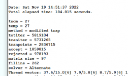
This is the Quad 405 with the timestep calculated manually and then run again using 10ns as a timestep. Look also at the numbers at the left, now I'm in the 10's of millions.

This is the Quad 405 with the timestep calculated manually and then run again using 10ns as a timestep. Look also at the numbers at the left, now I'm in the 10's of millions.
I set the timestep to something like {1/f/4096}, where .par f=1k, 10k, etc. and the stimulus frequency. .tran 0 {5/f} {1/f} {1/f/4096} .options plotwinsize=0 nothing more.
I fft the voltage source to check that it gives ~0% THD. If the source is 0% THD, then it's good enough, no point wasting time on a long simulation. But there are mysteries and changing things that should be irrelevant often make a big difference running the simulation, things like grounding and open nodes. When a simulation takes too long, I take it that the circuit is unstable and/or has other problems. Both sides of a transformer need a ground reference.
I fft the voltage source to check that it gives ~0% THD. If the source is 0% THD, then it's good enough, no point wasting time on a long simulation. But there are mysteries and changing things that should be irrelevant often make a big difference running the simulation, things like grounding and open nodes. When a simulation takes too long, I take it that the circuit is unstable and/or has other problems. Both sides of a transformer need a ground reference.
Last edited:

Can I upload an LTSpice simulation of a power supply and someone tell me if the variables I am using are correct or what values should I adjust?
You can attach a .asc directly. Just make sure it is self contained and will run on anyones system. If it uses special models put the whole thing in a zipped file and attach that.
Here are the files. I think the models used are not special and come with the original LTS install.
The error I get in Sulzer's is that V1 is not in the circuit. I enclosed a later Walt Jung redesign that shows noise curve alright.
The third simulation is for impedance curve. How do I get the vertical dimension to be in ohms?
Thanks!
The error I get in Sulzer's is that V1 is not in the circuit. I enclosed a later Walt Jung redesign that shows noise curve alright.
The third simulation is for impedance curve. How do I get the vertical dimension to be in ohms?
Thanks!
Attachments
Rename V2 to V1 in Sulzer. You need a V1 because the .noise directive refers to V1.
For impedance, plot V(out)/Ie(Q1). To get an ohms scale, right click in the axis area and select 'Linear' .
The 3rd has several non-LTspice models and will not run here (the transistors). See Mooly's post above.
Jan
For impedance, plot V(out)/Ie(Q1). To get an ohms scale, right click in the axis area and select 'Linear' .
The 3rd has several non-LTspice models and will not run here (the transistors). See Mooly's post above.
Jan
Last edited:
That's useful and smart! Thanks.I set the timestep to something like {1/f/4096}, where .par f=1k, 10k, etc. and the stimulus frequency. .tran 0 {5/f} {1/f} {1/f/4096} .options plotwinsize=0 nothing more.
I fft the voltage source to check that it gives ~0% THD. If the source is 0% THD, then it's good enough, no point wasting time on a long simulation. But there are mysteries and changing things that should be irrelevant often make a big difference running the simulation, things like grounding and open nodes. When a simulation takes too long, I take it that the circuit is unstable and/or has other problems. Both sides of a transformer need a ground reference.
What do you set the fft length to in the View|FFT dialog window?
Jan
OK,
Not renaming V2 was a distraction, which at my age shouldn't be surprising.
Plotting the impedance, adding V(out)/Ie(Q1) and getting the ohms scale worked like a charm.
I changed the IC. The transistors models are not on your list?
Sorry, I am rather rusted with LTS and I don't remember where I got them, if they are not standard.
My new intention was if you could check my simulations and results, now that you answered. 🙂
Someone on the Super-regulator thread commented there was only one LTS simulation of the reg. I can upload mine, which are plenty, for others to see and discuss.
Perhaps there can be other things to simulate.
Jan, many thanks.Rename V2 to V1 in Sulzer. You need a V1 because the .noise directive refers to V1.
For impedance, plot V(out)/Ie(Q1). To get an ohms scale, right click in the axis area and select 'Linear' .
The 3rd has several non-LTspice models and will not run here (the transistors). See Mooly's post above.
Jan
Not renaming V2 was a distraction, which at my age shouldn't be surprising.
Plotting the impedance, adding V(out)/Ie(Q1) and getting the ohms scale worked like a charm.
I changed the IC. The transistors models are not on your list?
Sorry, I am rather rusted with LTS and I don't remember where I got them, if they are not standard.
My new intention was if you could check my simulations and results, now that you answered. 🙂
Someone on the Super-regulator thread commented there was only one LTS simulation of the reg. I can upload mine, which are plenty, for others to see and discuss.
Perhaps there can be other things to simulate.
Attachments
- Home
- Design & Build
- Software Tools
- Installing and using LTspice IV (now including LTXVII), From beginner to advanced