Stuart did not say anything even remotely insensitive
There is no need for this tone! I never claimed using them is necessary.

There maybe a language barrier here.There is no need for this tone! I never claimed using them is necessary.
Please don't take offence. @OmeEd We are all trying to help each other out on this thread.
We also need to be mindful that for some members this is there first amplifier build. With that in mind we don't want new builders to read posts where they may conclude they need to do something extra outside the build guide.
We also don't want them to think that lf I add that extra aluminium plate it will some how improve things because it won't. The extra thermal resistance that is introduced will negate any possible gains it could provide. The fact that the two heatsinks are of equal size, thermal mass and each transistor pair is assembled in an alternate manner will ensure perfect heatsink thermal loading and heat dissipation.
An excellent point.The fact that the two heatsinks are of equal size, thermal mass and each transistor pair is assembled in an alternate manner will ensure perfect heatsink thermal loading and heat dissipation.
Best,
Anand.
... is the thermal resistance you are mentioning the one between the two heatsinks and the thermal spreader plate? what does "enourmous" mean? please consider that there is a plenty of square inches for thermal conduction, much more than between the devices and the heatsink itself. The thermal resistance is one parameter only, you have to consider the thermal contact area also ...Okay to experiment, but that's not the way. The thermal transition resistances are enormous. Thermal paste doesn't help either.
OmeEd.
I always use aluminum blocks like yours as heat spreader, works just fine. For sure the contact between the heat spreader and the heatsink will add a little bit of thermal resistance , but the actual thermal resistance for the heatsink + heatspreader will not be bigger than the thermal resistance of the heat sink by itself.As you said you can use the enclosure for a different project . You can test your amp having the board attached to the heat spreader only , we are experimenting and learning.
Tom from Neurochrome.com uses the heatpreader for an easy way to attach the amps (modulus 186/286/686) to the heatsink, I do believe that he did some measurements with and without that heatspreader.
OmeEd.
Currently we have an equal number of transistors on two equally sized heatsinks. The Heatsinks are made out of Aluminium and the heat spreader plate that you are talking about is also made out of aluminium. Please explain to all of us how this extra piece of plate is going to reduce all of the junction temperatures of the output transistors further than what they are already.
I see no way that the removal of heat from the junctions will be any better as both the heatsinks and the Aluminium plate will absorb and spread the heat at the same rate as there thermal conductivity is the same.
The extra plate will just create another unnecessary thermal barrier for the heat from the transistor junctions to pass through.
For @OmeEd I don't think it's about working better. It's about the ability to remove the amp module without dealing with all the thermal paste and being able to substitute different modules into the case for experimentation.
If that's the case. I completely support what he is doing.For @OmeEd I don't think it's about working better. It's about the ability to remove the amp module without dealing with all the thermal paste and being able to substitute different modules into the case for experimentation.
Hi Guy's,
I just posted a small update to the BOM which contains another option for C112.
Please download it from your Dropbox link when you have time.
This update applies to the 2nd GB boards only.
The update is noted in the revisions area at the bottom of the file.
I just posted a small update to the BOM which contains another option for C112.
Please download it from your Dropbox link when you have time.
This update applies to the 2nd GB boards only.
The update is noted in the revisions area at the bottom of the file.
Hello Stuart,We will send out shipping payment requests once we have the orders ready to go.
I haven't received the payment request yet. Is this still work in progress or I have missed a message from PayPal?
Sincerely
Last edited:
Excuse me for my ignorance. I am slowly taking up information about amplification types (between work, family and studies). I am aware class ab amplifiers can work in pure class a at low load levels. Is it the case with the Wolverine as well, and if yes, to what extent?
Thanks
Thanks
When it comes to class A operation it all becomes a matter of heat dissipation. The more you increase the bias the longer the amplifier will remain in the class A region. The output transistors also require larger levels of heat dissipation as the voltage drop collector to emitter increases in other words, higher rail voltage will also affect how far you can push the amplifier to remain in the class A region.Excuse me for my ignorance. I am slowly taking up information about amplification types (between work, family and studies). I am aware class ab amplifiers can work in pure class a at low load levels. Is it the case with the Wolverine as well, and if yes, to what extent?
Thanks
Now the question remains is that necessary. For the wolverine, no it's not. Some amplifiers dare I say aren't optimised and short cuts in there designed and layout topology were made due to various reasons.
The fall out from all this is that some of these short comings are reduced running the amplifier in the class A region.
The Wolverine's circuit is different. It has been designed to optimise all of the circuit building block elements.
Over the years there has been many people who have experimented, designed and tested different topologies and circuit building blocks to enhance amplifier performance. When the wolverine development team designed the circuit and layout of the pcb we have tried to use the lessons learnt in the past and glean and utilise as much information as possible to apply to this design.
Having said all that, and if I can be bold enough to say, the wolverine doesn't suffer from the same short comings that many amplifiers do. So running it in the class A region outside the parameters of the Oliver condition is unnecessary and is just wasting energy and generating more heat than necessary.
Barney Oliver of HP showed in 1971 that the optimum class AB bias point was that where
re ’ of the output devices equals the value of the emitter resistors. This amounts to biasing the output stage
so that 26 mV (kT/q) appears across the emitter resistors under the quiescent bias condition
In reality, the optimum value is a bit less than 26 mV because a few mV must be accounted for in the
effective ohmic emitter resistance of the power transistor. Hence the value of 22mV used in the biasing of the wolverines output stage.
I hope that helps to answer your question.
Thank you for the detailed response. I ll probably get one of those books on audio signal amplification too.
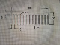
If this kind of a heatsink as shown on attached pictures is OK then it is available from temteccontrols seller on Australian EBay.
Lengths available up to 400mm. Plain aluminium not anodized.
Lengths available up to 400mm. Plain aluminium not anodized.
Attachments

Hi everyone,
Got home yesterday to find my Wolverine boards had arrived. I bought a set of the EF3-3 and EF3-4 in black. The boards really do look amazing, screen printing is clear and info on both sides of the board. The matt black with gold is a treat to view.
Just wanted to acknowledge Stuart and the team for the crazy amount of work that went into the design and now distribution and support.
I read through the Wolverine design thread to gain as much info as I could before building the amp. It quickly became apparent that most of the discussion all tho very interesting was above my understanding but it is clear how much time and knowledge was given by these guys.
Thanks
Jeremy T
Here we go. This will be the home for my Wolverine amp.
I will have to build my own version of modushop perforated m3 mesh tray. For that, I am itching to utilise a 3d printed (have access to ultimaker rig at work) standoffs which will hold cut to size 1.5 mm thick mesh m3/ 5mm pitch. Can potentially 3d print all fittings as an integrated frame (including two-sided conduits with a foil lining in between for twisted wire runs) using ABS plastic, however unsure how feasible that would be.
If not, will use standard aluminium angle brackets + aforementioned mesh and possibly encapsulate the toroidal transformer in its own enclosure (can be had from ebay etc).
Attachments
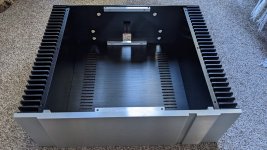
Pretty! 👍This will be the home for my Wolverine amp.
What are dimensions of your chassis and where have you purchased it?
Internal dimensions: W 330mm H 142mm D 350mm.
Got it on Aliexpress , bundled with an enclosure for my future IronPre preamp. Fedex door to door in 4 days.
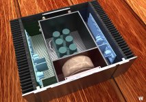
It seems H142 will let me to put toroidal on a side.
Got it on Aliexpress , bundled with an enclosure for my future IronPre preamp. Fedex door to door in 4 days.
It seems H142 will let me to put toroidal on a side.
If it fits (and if I am going to use a conventional power supply) , I plan to put transformer in front, on its side- attached to one of metal separators.
Does it make sense to add another chamber for power supply filter, thus effectively introducing 4 distinct isolated chambers?
Does it make sense to add another chamber for power supply filter, thus effectively introducing 4 distinct isolated chambers?
Attachments
- Home
- Amplifiers
- Solid State
- DIY Class A/B Amp The "Wolverine" build thread