And I never saw it. But thank you!Or was the original white? I'm not sure - I didn't use it!
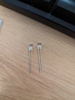
Turns out it was white, as I just found mine in the drawer. The forward voltage is slightly different (2.478v vs 2.208 for the green) but the form factor is identical (see attached - original on the left, green on the right).And I never saw it. But thank you!
Attachments
Insert the LED into your Mega328 component tester. It will tell you which pin is the anode and which pin is the cathode. Mega328 will also blink the LED a couple times during testing so you can see what color it glows.
eBay link . . . Amazon link . . .
eBay link . . . Amazon link . . .
IMO, white and blue LEDs are too bright as power-on indicators. A small 10ma green LED with 5ma will give a soft glow.
I inserted the LED in a piece of cable jacket to insert it suggly in the panel. It can be unplugged for service. The green LEDs are generic 10ma. The short lead is ground, the longer lead is "+". The red wire goes to a 2700 ohm resistor which is connected to +15 or +22 at R10. The black wire goes to R9.

I inserted the LED in a piece of cable jacket to insert it suggly in the panel. It can be unplugged for service. The green LEDs are generic 10ma. The short lead is ground, the longer lead is "+". The red wire goes to a 2700 ohm resistor which is connected to +15 or +22 at R10. The black wire goes to R9.
There are a couple of things to checkHi Everyone, I am trying to modified the Whammy Kit from original Talema Transformer to Primary 230V Transformer. As the primary voltage of new transformer is 230V only, how should I solder the transformer in the pcb? And How should I solder the jumper? Thanks.
Can the transformer fit / can it be soldered onto the PCB? Does it need new holes? Maybe post the part number of that transformer you are trying to use..?
Can you take a photo of the PCB underside of that area? I don't have that PCB and I am not sure how the mains voltage tracks are being laid on that board.
Out of curiosity; If someone wanted to wire a whammy to work like a power amp, with an external preamp / volume control, would it be possible?
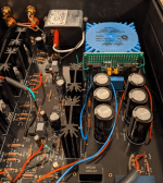
Just posting to say, after many, many weeks of chipping away at this between parenting, my Whammy is complete!
The slightly different components on the power section are due to my original board having a manufacturing issue (I got confirmation of a replacement board after I had completed and tested the power supply on the original, and replacement parts were cheaper than a desoldering gun). 😅
The removal of anodising near the bolt holes is intentional, fwiw, to ensure every panel is grounded.

Which opamp did you choose?Just posting to say, after many, many weeks of chipping away at this between parenting, my Whammy is complete!
The slightly different components on the power section are due to my original board having a manufacturing issue (I got confirmation of a replacement board after I had completed and tested the power supply on the original, and replacement parts were cheaper than a desoldering gun). 😅
The removal of anodising near the bolt holes is intentional, fwiw, to ensure every panel is grounded.
View attachment 1110706
Just the stock one for now, but I've mounted the caps either side underhung so that I can play with some big opamps if required (although that input cable might need to be rerouted if I do).Which opamp did you choose?
C13 gives you a comfortable feeling of reassurance and security, now that you have "bypassed" the two electrolytic capacitors in series, C17 and C12.
as Mark said, regular praxis of bypassing big elcos
and big elcos are boostrap for opto BJT, to keep voltage between gates constant, while they're jumping up and down, in music rhythm, while your feet are happily following
and big elcos are boostrap for opto BJT, to keep voltage between gates constant, while they're jumping up and down, in music rhythm, while your feet are happily following
technically yes
sound-wise, only you can tell
seriously - observe that single OP is used here
sound-wise, only you can tell
seriously - observe that single OP is used here
technically yes
sound-wise, only you can tell
seriously - observe that single OP is used here

Both are dual OPAmps in the DIL package, and are compatible. The muse has max. Vcc/Vee restrictions... but both will work fine.
technically yes
sound-wise, only you can tell
seriously - observe that single OP is used here
yup, ZM's brainfart
Whammy is using dual OPamp, so ..........
I have tried it. Just give it appropriate voltage.Is it safe to use MUSES01?
protect whammy opamp from overvoltage:
The Whammy build procedure gives 3 options for 7815 output voltage -- 15v, 17v, or 22v. This does not bother the MOSFETs but it could damage an opamp where the absolute maximum supply voltage is exceded. I believe that the opamp supply should be fixed at 15v so that variations in 7815 MOSFET settings or transformers do not cause faults.
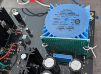
I modified the Whammy with 7815,7915 regulators just for the opamp. I installed a gridded PCB by drilling holes in the non-functional fins of the toroidal transformer. I lifted the hot side of R35 and R36 so that the opamp is powered by it's own regulators.
Be aware that the MOSFET regulators suffer more stress when a higher voltage toroid is used. This occurs because of the increased voltage across the linear regulators. Also, the vertical heatsinks on the main board are not very effective without a cooling fan.
The Whammy build procedure gives 3 options for 7815 output voltage -- 15v, 17v, or 22v. This does not bother the MOSFETs but it could damage an opamp where the absolute maximum supply voltage is exceded. I believe that the opamp supply should be fixed at 15v so that variations in 7815 MOSFET settings or transformers do not cause faults.
I modified the Whammy with 7815,7915 regulators just for the opamp. I installed a gridded PCB by drilling holes in the non-functional fins of the toroidal transformer. I lifted the hot side of R35 and R36 so that the opamp is powered by it's own regulators.
Be aware that the MOSFET regulators suffer more stress when a higher voltage toroid is used. This occurs because of the increased voltage across the linear regulators. Also, the vertical heatsinks on the main board are not very effective without a cooling fan.
Attachments
- Home
- Amplifiers
- Pass Labs
- "WHAMMY" Pass DIY headphone amp guide