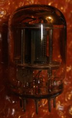
As I recall it was pretty much invisible. I've noticed the same thing when I've had other "battery" tubes on the breadboard, very little glow and they don't warm up much at all even after being run for a long time.I also removed the aluminium shield. But funny thing is that, I cannot see the flame of the filament and all the measure are not quite right. Can you see the flame of the filament? Maybe I am not lucky enough and bought some flawed tubes.
You should be able to measure the voltage at the socket, however.
I want to know if you can mount the 2P29L horizontally, and if so what is the orientation. Any ideas?
If it's the case that a flat anode should be orientated vertically, what does this correspond to in the pinout? Can anyone who has taken the metal can off post a pic or describe the pinout?
If it's the case that a flat anode should be orientated vertically, what does this correspond to in the pinout? Can anyone who has taken the metal can off post a pic or describe the pinout?
Hello Bela! Where do you get this information from? I'd really like to know.Must to use filament is vertical.
Own experience.
I lost hundred years tube, when it decided (tested in not fixed socket) to wrong direction and the sagged filament contacted to grid. 😢
From this point of view the most sensitive filament type is in right.

If you use this horizontally the hot filament sagging, and can be soldered together to the transport rod.
The "M" or 'W" type (spring tensioned) filament is more tolerant.
I lost hundred years tube, when it decided (tested in not fixed socket) to wrong direction and the sagged filament contacted to grid. 😢
From this point of view the most sensitive filament type is in right.
If you use this horizontally the hot filament sagging, and can be soldered together to the transport rod.
The "M" or 'W" type (spring tensioned) filament is more tolerant.
Last edited:
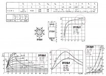
2Ж27Л, 2П29Л, 4П1Л - военные, работают в любом положении.
Attachments
Last edited:
Translation: 2J27L, 2P29L, 4P1L are military tubes, they work in any position.2Ж27Л, 2П29Л, 4П1Л - военные, работают в любом положении.
Excellent! Thanks so much and this confirms my hunch that these were used in portable equipment for field use. I suspected they were designed and tested for use in all orientations.
Just a question about how to connect screen and grid 3 on the 2P29L. I've been using 100R resistors and connecting both to the anode. So:
- Do you need any resistors at all if running the tube at around 150V on the anode?
- Any reason to connect grid 3 to the cathode or just connect both to the anode?

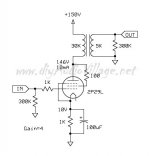
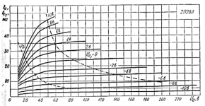
Max g2 voltage 150V, max g2 dissipation 0.7W. There are no curves in the datasheet to estimate g2 current at 150V, but taking into account that g2 voltage will never be higher than the anode I would say you are pretty safe connecting g2 directly to the anode.
Attachments
Last edited:
The lamp has different characteristics from the years of release. For example, if the anode has a permissible voltage of 150 volts, then on the second grid 120. In the passports under the above link, this is visible.
Last edited:
I have some basic Russian and this particular data says max voltages are 200 anode and 150 screen, dissipation 2W and 0.7W. Grid 3 at 0V. I don't know how to tell if the valves I have conform to this. Mine are in green boxes and appear to say "laipa" or launa on the box.
Any preference for grid 3 connected to cathode or anode via 100R?

There is a pre-amp at Bartola's (https://www.bartola.co.uk/valves/tag/2p29l-preamp/) that uses g2 and g3 tied to the plate with a 300 ohm resistor.I have some basic Russian and this particular data says max voltages are 200 anode and 150 screen, dissipation 2W and 0.7W. Grid 3 at 0V. I don't know how to tell if the valves I have conform to this. Mine are in green boxes and appear to say "laipa" or launa on the box.
Any preference for grid 3 connected to cathode or anode via 100R?
View attachment 1103728
Hi Andy - Yes, the lower-case characters take a little more practice! It says Лампа - Lampa (Valve).Mine are in green boxes and appear to say "laipa" or launa on the box.
Try the 3rd grid both ways, if you like to be sure. Connected to cathode is normal, but you can try it as Ale's method.
There is no reason to connect g3 to cathode, if g2 is connected to anode. When g3 is connected to anode, gm of the tube is higher.
- Any reason to connect grid 3 to the cathode or just connect both to the anode?

- Home
- Amplifiers
- Tubes / Valves
- 2P29L Preamp