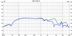
In that case it's a matter of guesstimating levels anyway and sticht the two "by eye".I needed nearfield measurement to merge it with my spatial farfield measurements
Anything above 200Hz or so isn't relevant or anything above the bafflestep region to be more specific.
Also, in that case 5mm is maybe a little to close actually.
Anyhow, the wavelengths of those frequencies definitely don't care much about many obstacles.
If you line the two up, they are basically identical for the low frequency part
Attachments

Sorry for this newbie question,
I have spl traced my woofer and tweeter,
I have just entered the tweeter spl graph ,
Right now just want to play and see what happens,
But when I add in parts nothing changes?
Am I missing a setting
I do have a mtm design I want to fully build , and test but fig baby steps
Jeremy
I have spl traced my woofer and tweeter,
I have just entered the tweeter spl graph ,
Right now just want to play and see what happens,
But when I add in parts nothing changes?
Am I missing a setting
I do have a mtm design I want to fully build , and test but fig baby steps
Jeremy
Member
Joined 2003
Not enough information to know the spefics steps you've taken. Likely, the crossover circuit is incomplete.
Power / groundNot enough information to know the spefics steps you've taken. Likely, the crossover circuit is incomplete.
Amp / speaker
In the spl window I load the file ( spl ) that I traced.
If I drop in 4 resistors and ground them , nothing changes
I added grounds to all the restors,The red dots indicate no connection. Also your capacitor is grounded on both ends and essentially not doing anything.
I am just playing trying to get it to move ?
You've almost got a short circuit there with all those resistors in parallel. makes no sense!
Member
Joined 2003
Basic electronics would be my guess...I added all that and nothing changes?
Obviously I am missing something
Since you've got a tweeter response loaded, start with a basic high pass. You don't even need to bother loading a frequency response in there.
Attachments

I am just playing trying to get it to move ?
A driver's frequency response is altered by altering the voltage applied to the driver. We have to put a reactive element in series with the driver in order to alter the voltage... i.e. a capacitor or inductor. In your circuit you have elements only in parallel with the driver, and these can change the impedance seen by the amp, but they do not change the voltage as seen by the driver.
There are 5 resistors with a red dot on bottom connection, why? The capacitor is connected to ground on both ends, why?
You have your driver connected directly to the amplifier. This is a low impedance point and nothing you do here will change the Voltage seen at that point so the driver will see only what the amplifier does. This is the function of a Voltage amplifier.I added all that and nothing changes?
Obviously I am missing something
Rather than this, you should try using a series component first. This turns the other side into a higher impedance node where Voltages can be manipulated. Only after establishing a reasonable impedance should you begin sending components to ground.
I will put in my current xover tonight for my speaker,You have your driver connected directly to the amplifier. This is a low impedance point and nothing you do here will change the Voltage seen at that point so the driver will see only what the amplifier does. This is the function of a Voltage amplifier.
Rather than this, you should try using a series component first. This turns the other side into a higher impedance node where Voltages can be manipulated. Only after establishing a reasonable impedance should you begin sending components to ground.
See what happens
This is one of the crossovers ( sb audience 65cnd-t) for my speaker,
I am just using trace function right now,
This is my first
Time trying all this
You are approaching this forum far beyond your current understanding of electronics fundamentals. I'm sorry to to say that. It's just true.View attachment 1099406
This is one of the crossovers ( sb audience 65cnd-t) for my speaker,
I am just using trace function right now,
This is my first
Time trying all this
100% agree Paul,You are approaching this forum far beyond your current understanding of electronics fundamentals. I'm sorry to to say that. It's just true.
Unfortunately this is my starting point ,
I am try to solve a puzzle I have zero understanding,
But the great thing about these forms, there is always someone will to.take the time to.help ,
We all have been that guy
A starting point is part of the process no matter what the subject. Just start at the right point. It's not unfortunate. It just 'is what it is'.100% agree Paul,
Unfortunately this is my starting point ,
I am try to solve a puzzle I have zero understanding,
But the great thing about these forms, there is always someone will to.take the time to.help ,
We all have been that guy
I have more than 3 decades of experience in pro audio. Vituixcad is new for me.
Start with I = E/R. There is an important relationship with these three values.
Last edited:
Absolutely.We all have been that guy
Perhaps what this needs is a fresh thread in the Multi-Way forum where you can explore your circuit development skills. A thread like that could include simulations which show you the results to watch out for, what to avoid and what to do.
This also keeps this thread on-topic for issues directly related to Vituixcad.
https://www.diyaudio.com/community/forums/multi-way.6/
- Home
- Design & Build
- Software Tools
- VituixCAD