Hi Guy's
In a continuing effort to improve the wolverine amplifier we investigated offering 2 input impedance options.
The original input impedance is approximately 22K Ohms.
The second and new option which we have thoroughly tested is approximately 10K Ohms.
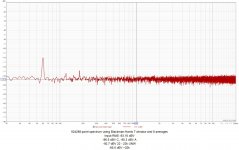
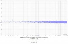
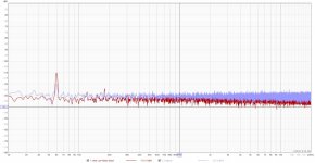
One of the advantages of lowering the input impedance is the reduction in the amplifiers noise floor.
From our tests results we were successful in reducing the noise floor from -90.42dB to -93.16bB across a frequency band of 20hz-20khz.
The open loop gain remains the same.
I have updated the BOM in the Dropbox folder so you can see the component changes for those who wish to change their input impedance.
A big thank you goes out to the rest of the wolverine team and especially @fireanimal and @danieljw for all their extensive testing to bring this
option to all Wolverine project members.
In a continuing effort to improve the wolverine amplifier we investigated offering 2 input impedance options.
The original input impedance is approximately 22K Ohms.
The second and new option which we have thoroughly tested is approximately 10K Ohms.
One of the advantages of lowering the input impedance is the reduction in the amplifiers noise floor.
From our tests results we were successful in reducing the noise floor from -90.42dB to -93.16bB across a frequency band of 20hz-20khz.
The open loop gain remains the same.
I have updated the BOM in the Dropbox folder so you can see the component changes for those who wish to change their input impedance.
A big thank you goes out to the rest of the wolverine team and especially @fireanimal and @danieljw for all their extensive testing to bring this
option to all Wolverine project members.
Attachments

Hi Scott, Is there any news from your parents regarding there wolverine gift?
stuartmp & Co.:
Yes, actually. I spoke with my parents a couple of days ago and they were ecstatic about the improvement to their stereo! The Gainclone that I built for them in 2005 was reliable but no sonic match for the Wolverine-based integrated amp I gave them a few weeks ago. The stereo is located in a large combination art studio and reading nook measuring roughly 5.5 meters (18') by 6.5 meters (21'), with a cathedral ceiling that at its peak is probably 4.5 meters (15') high. The space is pretty reflective (lots of brick and glass surfaces and a hardwood floor) and the speakers are wall mounted, which affects their bass response. Even so, when I installed the amp its superiority over the Gainclone was abundantly clear (though I mentioned nothing to my parents). Music is much more "present" in the room now and is detailed, wonderfully resolved and rich. My parents, who typically spend 4-6 hours a day in that room, told me that they find themselves in the studio for longer periods these days because the music is so inviting. They remarked specifically about the improved clarity, depth and resolution (though not necessarily in those words) and are very happy with their gift.
Kudos, again, to the Wolverine design team!
Regards,
Scott
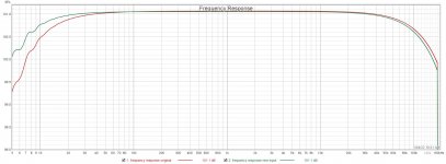
Stuart, are you sure that you have not reversed the annotations on the frequency response plot? The LF roll off should move up in frequency when R2 is reduced, not down.Hi Guy's
In a continuing effort to improve the wolverine amplifier we investigated offering 2 input impedance options.
The original input impedance is approximately 22K Ohms.
The second and new option which we have thoroughly tested is approximately 10K Ohms.
One of the advantages of lowering the input impedance is the reduction in the amplifiers noise floor.
From our tests results we were successful in reducing the noise floor from -90.42dB to -93.16bB across a frequency band of 20hz-20khz.
The open loop gain remains the same.
I have updated the BOM in the Dropbox folder so you can see the component changes for those who wish to change their input impedance.
A big thank you goes out to the rest of the wolverine team and especially @fireanimal and @danieljw for all their extensive testing to bring this
option to all Wolverine project members.
Keith
Hi Keith,Stuart, are you sure that you have not reversed the annotations on the frequency response plot? The LF roll off should move up in frequency when R2 is reduced, not down.
Keith
Please refer to the BOM as there is a list of component changes not just R2.
What a wonderful result Scott.stuartmp & Co.:
Yes, actually. I spoke with my parents a couple of days ago and they were ecstatic about the improvement to their stereo! The Gainclone that I built for them in 2005 was reliable but no sonic match for the Wolverine-based integrated amp I gave them a few weeks ago. The stereo is located in a large combination art studio and reading nook measuring roughly 5.5 meters (18') by 6.5 meters (21'), with a cathedral ceiling that at its peak is probably 4.5 meters (15') high. The space is pretty reflective (lots of brick and glass surfaces and a hardwood floor) and the speakers are wall mounted, which affects their bass response. Even so, when I installed the amp its superiority over the Gainclone was abundantly clear (though I mentioned nothing to my parents). Music is much more "present" in the room now and is detailed, wonderfully resolved and rich. My parents, who typically spend 4-6 hours a day in that room, told me that they find themselves in the studio for longer periods these days because the music is so inviting. They remarked specifically about the improved clarity, depth and resolution (though not necessarily in those words) and are very happy with their gift.
Kudos, again, to the Wolverine design team!
Regards,
Scott
I'm so happy that your parents are enjoying there special gift.
As far as I know the SIP2 connector is intended to connect to a security circuit. The voltage over R120AB and R123AB, independently or in combination, can be used to detect fault conditions. I'm not aware of an existing circuit tailored for the Wolverine amplifier, but Douglas Self gives an example of such a circuit in his book Audio Power Amplifier Design.

just for a change decided on copper heatsinks, don't have a pro setup to do metal work...bit of finishing work required🙄
 but all with hand tools
Hi Guy's,
I found a small error on the Schematics attached to the 1st post. I have now updated them.
I have also added the Sprint Layout Template for the 'IPS board' for anyone who wishes to design there own IPS board.
I found a small error on the Schematics attached to the 1st post. I have now updated them.
I have also added the Sprint Layout Template for the 'IPS board' for anyone who wishes to design there own IPS board.
Last edited:
Considering the total cost of the project, why take the risk? If 0.22 ohm is optimal, then 0.33 ohm is 50% to high.One quick question: would it matter much if I replaced 0.22 ohm 5W emitter resistors in the output with 0.33ohm 5W emitter resistors?
0.33ohms would not be ideal as the output impedance will higher so your distortion levels would increase.One quick question: would it matter much if I replaced 0.22 ohm 5W emitter resistors in the output with 0.33ohm 5W emitter resistors?
I have plenty of these 0.33ohm/5W low inductance resistors; their inductance is about 0.05uH at 10kHz.
thank you,
cheers
0.22ohms is the ideal value. If you really want to, two 0.33 in parallel would be better than a single 0.33ohm but you would want to ensure that your output transistor are closely matched.
As you probably know these emitter resistors help the output transistor load share and thermal track when they have difference gain values.
If they are not matched one transistor will do more work than rest and that transistor will explode. Subsequently the rest of the transistors will exploded. :-(
My recommendation would be to use the components listed on the bom. We have done and continue to do extensive testing and the components listed on the BOM are a result of those tests.
Thanks Stuart,0.33ohms would not be ideal as the output impedance will higher so your distortion levels would increase.
0.22ohms is the ideal value. If you really want to, two 0.33 in parallel would be better than a single 0.33ohm but you would want to ensure that your output transistor are closely matched.
As you probably know these emitter resistors help the output transistor load share and thermal track when they have difference gain values.
If they are not matched one transistor will do more work than rest and that transistor will explode. Subsequently the rest of the transistors will exploded. :-(
My recommendation would be to use the components listed on the bom. We have done and continue to do extensive testing and the components listed on the BOM are a result of those tests.
I know that output impedance would somewhat rise and distortion somewhat increase but this amp has distortion levels very low while low inductance of emitter resistors minimizes chances for oscillation. In HB I matched all transistors so I used 0.18ohm emitter resistors instead of 0.22ohm. Unfortunately over time my stock of transistors got smaller and matching became less precise. The real question is now which trade off is practically more acceptable.
So maybe I rephrase may question:
would it be better if I use ordinary 0.22ohm resistors which have higher inductance (I have plenty of these) rather than low inductance 0.33ohm ones?
cheers,
I think I answered your question. My recommendation would be to use the components listed on the bom.Thanks Stuart,
I know that output impedance would somewhat rise and distortion somewhat increase but this amp has distortion levels very low while low inductance of emitter resistors minimizes chances for oscillation. In HB I matched all transistors so I used 0.18ohm emitter resistors instead of 0.22ohm. Unfortunately over time my stock of transistors got smaller and matching became less precise. The real question is now which trade off is practically more acceptable.
So maybe I rephrase may question:
would it be better if I use ordinary 0.22ohm resistors which have higher inductance (I have plenty of these) rather than low inductance 0.33ohm ones?
cheers,
Going outside of this will increase your distortion which you appear to be well aware of. How much its hard to say.
The higher inductance of your stock 0.22ohm resistor will also change you phase and gain margins which may in turn lead to instability and the further need to increase your compensation capacitors C4, C5. This will in turn lower your loop gain and once again cause a increase in distortion.
Ultimately its up to you. If I had to choose I would pick the low inductance option 2 x 0.33ohms in parallel and match my outputs as best that I could.
Thank you Stuart,I think I answered your question. My recommendation would be to use the components listed on the bom.
Going outside of this will increase your distortion which you appear to be well aware of. How much its hard to say.
The higher inductance of your stock 0.22ohm resistor will also change you phase and gain margins which may in turn lead to instability and the further need to increase your compensation capacitors C4, C5. This will in turn lower your loop gain and once again cause a increase in distortion.
Ultimately its up to you. If I had to choose I would pick the low inductance option 2 x 0.33ohms in parallel and match my outputs as best that I could.
It's difficult to get low inductance 5W resistors without paying extra. I have 0.22 and 0.25ohm resistors with measured inductance of 0.1uH at 10kHz and 0.05uH at 100kHz, the difference is the result of meter displaying more significant decimal points with higher frequency tests. But you are right, the amp is so good that there is no point in saving on important components. I'll get low inductance 0.22ohm resistors for it.
With EF3 I'll probably use MG6311/9411 transistors and with EF4 I'll use less powerful njw1302/3281 or sanken 2sa2223a/sc6145a as 4 pairs should allow for 4ohm loading without problems. With 3 pairs more powerful MGs also should do.
cheers,
The MG6311/9411 are not on the tested list on the second sheet of the BOM.Thank you Stuart,
It's difficult to get low inductance 5W resistors without paying extra. I have 0.22 and 0.25ohm resistors with measured inductance of 0.1uH at 10kHz and 0.05uH at 100kHz, the difference is the result of meter displaying more significant decimal points with higher frequency tests. But you are right, the amp is so good that there is no point in saving on important components. I'll get low inductance 0.22ohm resistors for it.
With EF3 I'll probably use MG6311/9411 transistors and with EF4 I'll use less powerful njw1302/3281 or sanken 2sa2223a/sc6145a as 4 pairs should allow for 4ohm loading without problems. With 3 pairs more powerful MGs also should do.
cheers,
@jjs found the datasheets and I'm not sure they are the best output for the job. The FT is quite low at low collector currents and the cob is 500pf
maybe ask @jjs for his thoughts. The slower the outputs, the more chance there will be oscillation especially with a triple. That's why we tested the ones in the table for everyone and only put the ones that will work in the list. There were many that we tested that did not make the list.
Last edited:
MGs have lower cob, especially NPN (250pF) which generally works better, SOA of MGs is better which is better with lower number of outputs, however, as you say lower FT vs Ie of MGs might be of some concern.The MG6311/9411 are not on the tested list on the second sheet of the BOM.
@jjs found the datasheets and I'm not sure they are the best output for the job. The FT is quite low at low collector currents and the cob is 500pf
maybe ask @jjs for his thoughts. The slower the outputs, the more chance there will be oscillation especially with a triple. That's why we tested the ones in the table for everyone and only put the ones that will work in the list. There were many that we tested that did not make the list.
Looking at plots FT vs Ie of PNP MG and njw versions are not that much different although njw is somewhat better between 300mA and 3A, NPN versions show larger differences in favour of njw or mjl, true but how much would it matter? In HB MGs with triple outputs work very well but I ask Jeremy. I do not know if you tested MGs as these have not been produced for a few years by now. Anyway thanks for you comments. I'll ask Jeremy, I guess jjsl is him.
Unless Jeremy says NO I'll make a test, use MGs without soldering them in so my board won't be potentially damaged by soldering in and out and see what happens
cheers,
MGs have lower cob, especially NPN (250pF) which generally works better, SOA of MGs is better which is better with lower number of outputs, however, as you say lower FT vs Ie of MGs might be of some concern.
Looking at plots FT vs Ie of PNP MG and njw versions are not that much different although njw is somewhat better between 300mA and 3A, NPN versions show larger differences in favour of njw or mjl, true but how much would it matter? In HB MGs with triple outputs work very well but I ask Jeremy. I do not know if you tested MGs as these have not been produced for a few years by now. Anyway thanks for you comments. I'll ask Jeremy, I guess jjsl is him.
Unless Jeremy says NO I'll make a test, use MGs without soldering them in so my board won't be potentially damaged by soldering in and out and see what happens
cheers,
The MG6331/9411's will work well go ahead and use them. These parts are still plenty fast, their Ft still manages 16-17MHz at 100mA bias. Maybe you'll have to increase C4/C5 but I doubt it. I've simmed with 4MHz Ft parts and those are fine except they don't turn off so well at high frequencies which could lead to cross conduction and destruction of the of the Output stage.
Onsemi is sneaky on their datasheet, they specify the maximum cob for both npn and pnp transistors leading you to believe they are matched. Typically the pnp cob is about 2x the npn cob.
Jeremy
- Home
- Amplifiers
- Solid State
- DIY Class A/B Amp The "Wolverine" build thread