I’m really enjoying the preamp. ra7 did a great job. I need to put some bigger heat sinks on some of the transistors. The ones I’m using are a little small.
The only issue I need to sort out is I’m getting some 60hz noise in the left channel and some white noise in the right. You can only hear it when you put your ear right up the the speakers. From the listening position you can’t hear it. Even using the SCG in the desktop setup I can’t hear noise unless putting my ears right up to the speakers.
I will eventually try to eliminate the noise. Right now I’m enjoying how it makes everything sound. Almost like a tube pre.

I like the idea of EI transformers in low level circuits. I missed these HAMMONDS entirely. Thanks.
So good to hear!I’m really enjoying the preamp. ra7 did a great job. I need to put some bigger heat sinks on some of the transistors. The ones I’m using are a little small.
The only issue I need to sort out is I’m getting some 60hz noise in the left channel and some white noise in the right. You can only hear it when you put your ear right up the the speakers. From the listening position you can’t hear it. Even using the SCG in the desktop setup I can’t hear noise unless putting my ears right up to the speakers.
I will eventually try to eliminate the noise. Right now I’m enjoying how it makes everything sound. Almost like a tube pre.
For the 60 hz hum, you might try connecting the chassis to the ground on the PCB. That did it for me. Tip from Vunce and others. With a pot on the input, I was getting hum at the 2/3rd position. But the chassis to power ground cured it. You can connect directly or create a little barrier with a thermistor or a 10 ohm resistor between the two points. Of course the chassis MUST be connected to earth at the AC inlet to the preamp—that’s very important for safety.
Latest set of measurements.
Frequency response. Nothing surprising. -3 db point is below 10 Hz and above 50 kHz.

2.83 Vrms out. No attenuation applied. This one uses a EI core trafo that does produce more noise in the chassis, but still all the PS noise is below 100 db.

20Vrms out, 10:1 attenuation. That is about 56 V peak-to-peak. This will drive an F4 to full power. Higher harmonics show up, but look at that second. It masks the others and the total isn't that much higher than at 10Vrms (not shown, 0.11%). In these pages, Ben (@Ben Mah) had hypothesized that the SCG's distortion may not be rising, as opposed to the 300B, whose distortion was rising with level and gave me the perception of being overly sweet. I think these charts confirm the hypothesis.

Frequency response. Nothing surprising. -3 db point is below 10 Hz and above 50 kHz.
2.83 Vrms out. No attenuation applied. This one uses a EI core trafo that does produce more noise in the chassis, but still all the PS noise is below 100 db.
20Vrms out, 10:1 attenuation. That is about 56 V peak-to-peak. This will drive an F4 to full power. Higher harmonics show up, but look at that second. It masks the others and the total isn't that much higher than at 10Vrms (not shown, 0.11%). In these pages, Ben (@Ben Mah) had hypothesized that the SCG's distortion may not be rising, as opposed to the 300B, whose distortion was rising with level and gave me the perception of being overly sweet. I think these charts confirm the hypothesis.
How much voltage do you recommend from the raw supply?
I have no idea how much the 123 volts zener string affects the noise from the multiplier.
I read an article that said zeners are quiet if they do not exceed their voltage rating. If that matters here it would seem having the input voltage as close as possible to 123 volts. Without extra voltage they would no longer act as regulators but as a stop at 123 volts. But shoudl introduce minal noise into the supply voltage.
Does this make any sense?
The zener string regulates the voltage to 123V, so voltage in excess of 123V is needed for the regulation to be effective. The amount of excess voltage needs to take into consideration voltage fluctuations from the wall. Excess voltage is dropped by the 6k8 resistor preceeding the zeners. The higher the excess voltage, the higher current flow through the resistor and subsequently through the zener string. The resistor is sized so that the current needed to drop the excess voltage when it is at its maximum does not cause the zeners to exceed their power dissipation rating (derated for low heat and long life).
The minimum voltage feeding the resistor and zeners needs to be higher than 123V when the wall voltage is at its lowest.
As for zener noise, my understanding is that lower voltage zeners are less noisy than higher voltage zeners. Having filtering (C or RC) after the regulation also reduces noise.
The minimum voltage feeding the resistor and zeners needs to be higher than 123V when the wall voltage is at its lowest.
As for zener noise, my understanding is that lower voltage zeners are less noisy than higher voltage zeners. Having filtering (C or RC) after the regulation also reduces noise.
Last edited:
Thanks Ben! That pretty much answers all of Rick's questions. There is filtering for zener noise. See C13.
The minimum voltage above the zener string is the Vgs of the MOSFET. I would shoot for at least 7-10V above the zener string.
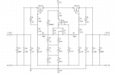
The schematic below shows the zener string total as 100V, which should be enough, but you can go higher than that. Lower than 100V is not recommended. I just used the parts I had on hand and ended at 112V.

The minimum voltage above the zener string is the Vgs of the MOSFET. I would shoot for at least 7-10V above the zener string.
The schematic below shows the zener string total as 100V, which should be enough, but you can go higher than that. Lower than 100V is not recommended. I just used the parts I had on hand and ended at 112V.
Last edited:
How much voltage from the raw supply?
Preamp circuit needs 100V minimum. Regulator needs 7-10V, say 10V. So, that's 110V. Plus a few for filtering (R11).
If you had a 100V secondary on the transformer, it would give you about 140 V out. At 35 mA total current draw (reg, circuit), R100 will drop 3.5V, say 4V. That would still put you well clear of the 110V target.
So, transformer secondary should be between 100-120V. The more the difference between the reg input and output, the bigger the heatsink on the reg FET. Currently, I have a little clip on sink.
A word on the regulator: This is a classic zener follower regulator, where the output of the FET on the source pin follows the input on the gate. And we fix the gate input with the zener string and kill the noise with C13. It is pretty much the same from the BOZ and BOSOZ preamps from Papa. In my testing with the SCG, it sounds as good as a shunt reg (I have one from K&K audio, based on Salas's shunt regs).
@ra7, any reason why you deliberately leave out the Rs1 value in the snubber circuit?Thanks Ben! That pretty much answers all of Rick's questions. There is filtering for zener noise. See C13.
The minimum voltage above the zener string is the Vgs of the MOSFET. I would shoot for at least 7-10V above the zener string.
The schematic below shows the zener string total as 100V, which should be enough, but you can go higher than that. Lower than 100V is not recommended. I just used the parts I had on hand and ended at 112V.
View attachment 1096130
In order to get an accurate Rs1 value, the transformer should be tested on the Quasimodo jig and oscilloscope.
https://www.diyaudio.com/community/...rmer-snubber-using-quasimodo-test-jig.243100/
I include the snubber components only if I Quasimodo’ed the trafo. Otherwise i omit them.
https://www.diyaudio.com/community/...rmer-snubber-using-quasimodo-test-jig.243100/
I include the snubber components only if I Quasimodo’ed the trafo. Otherwise i omit them.
Anyone willing to part with a completed resistor-loaded version, prefferably built with good parts ?
I know that for the zener string, to act as a regulator, the voltage would need to be more than the value of the zener string.
These are not exactly low voltage zeners. When I think low voltage I presume under 12 volts. I have no idea how the industry classifies them. Would the trick thing to do to use ten 12 volts zeners in series?
I have no idea how much of the zener noise gets past the mosfet so I have no idea how much the zener noise matters at all.
I was thinking of more of an over voltage protection versus regulation with the zeners to reduce their noise, if it is even a factor.
I have found that these noises are the kind you do not notice until they are gone. Which prompted me to consider zener noise and how to minimize it.
Easy enough to try them as a regulator and an over voltage limiter and hear if there is any difference.
My take on SCG (thanks Rahul for this gem).
PSU: after a transformer 24+24 VAC (chosen because of its availability - and therefore cheap price...)
 I've put a voltage doubler, for a VCC of 115V about. The raw VCC is then filtered and stabilized by a regulator - not so different from ra7's one: (schematic published on italian magazine - Costruire HiFi issues 48-49-50). An interesting feature is that it has double output, but voltage reference is shared. Pictures will follow...
PSU: after a transformer 24+24 VAC (chosen because of its availability - and therefore cheap price...)
Attachments
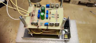
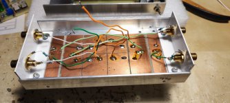
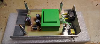
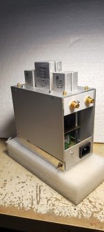
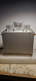
This is my multi-level car park 😉
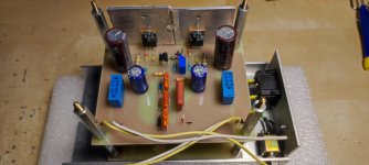
Ground floor: Trafo and voltage doubler
First floor: V regulator (2 x 100VCC)
Second floor: SCG
Flat roof: input and output capacitors (parallel of 2 ERO MKC on input, Polypro 12uF on output).
All the aluminum parts has been cut by hand, the PCBs are handmade. Cabling in the purest rat nest style...
Attachments
 Just brilliant! More than one way to make a beauty! Extra points for handcrafted PCB and chassis.
How does it sound?
Noise is relative. The zener noise may be high relative to other voltage references but is it high compared to the power supply ripple before regulation? I would think that in most cases the pre-regulated power supply ripple would be higher than the zener noise. Pre-regulated power supply noise would probably be in the mV range but zener noise would probably be in the uV range. Now R12 and C13 in ra7's circuit will behave as a RC filter so that would reduce some of the ripple.I know that for the zener string, to act as a regulator, the voltage would need to be more than the value of the zener string.
These are not exactly low voltage zeners. When I think low voltage I presume under 12 volts. I have no idea how the industry classifies them. Would the trick thing to do to use ten 12 volts zeners in series?
I have no idea how much of the zener noise gets past the mosfet so I have no idea how much the zener noise matters at all.
I was thinking of more of an over voltage protection versus regulation with the zeners to reduce their noise, if it is even a factor.
I have found that these noises are the kind you do not notice until they are gone. Which prompted me to consider zener noise and how to minimize it.
Easy enough to try them as a regulator and an over voltage limiter and hear if there is any difference.
So it seems to me that if the power supply feeding the zeners is quieter than the zeners, then the regulated output would be noisier. However if the power supply feeding the zeners is noisier than the zeners, then the regulated output would be quieter.
If the pre-regulated voltage is lower than the zener voltage, then the zeners are not in the circuit, but the R12 and C13 RC filter still does its filtering and the mosfet still does its thing. So the voltage at the mosfet source will have less ripple than the input voltage because of the RC filter, but this noise level will be what it is, with no reduction if it is higher than the zener noise. The output voltage would still be input voltage minus mosfet Vgs, but with no regulation.
As for noise and the mosfet, the mosfet is working as a follower so whatever voltage profile it sees at its gate is passed through to its source, and it probably adds a bit of its own noise.
This is diy so experimenting can be worthwhile and also educational. There are other factors that affect noise though so the whole build needs to be quiet enough in order for any differences to show.
Thank you Rahul, you deserve the merits, I only did the handcrafts. Sound is excellent, I can confirm
How does it sound?
Thank you Vunce for your kind words! That's DIY!Super Cool DIY work Guido!
- Home
- Amplifiers
- Pass Labs
- Schade Common Gate (SCG) Preamp