When using a digital source with a DAC, one can do many things.To compare apples to apples :
If one were to apply an LPF to a "normal" DAC, one can also do the same to a Viktor, or an AP for that matter.
I have not come across a DAC that does -150 dB H2 and -155 dB H3.
I also have a hard time building a LPF that does -155dB THD.
Cheers,
Patrick
The most straightforward one, is using two channels, of which one is inverted.
Of the second channel the fundamental is suppressed with a notch, leaving only the harmonics.
Those two channels are than summed as well as followed by a lowpass filter.
A bandpass can also be used to get rid of any hum or lower band noise.
This idea can also be done pure analog of course.
The biggest contribution in the THD here are obviously the opamps as well as the capacitors and how well the two channels are matched. One channel can also be used I guess, although compensating for any group delay is a little more tricky.
As for the LPF, I would use one with an higher Q. In our case we are only interested in one frequency.
So in this case it boosts the fundamental to higher order harmonics ratio a bit more.
You have to be careful with stability as well as clipping.
The summing as well as LPF part can basically be done all in one stage.
Last edited:
These techniques usually do not work because of the strong temperature dependency. There is always an imbalance.When using a digital source with a DAC, one can do many things.
The most straightforward one, is using two channels, of which one is inverted.
Of the second channel the fundamental is suppressed with a notch, leaving only the harmonics.
Those two channels are than summed as well as followed by a lowpass filter.
A bandpass can also be used to get rid of any hum or lower band noise.
This idea can also be done pure analog of course.
The biggest contribution in the THD here are obviously the opamps as well as the capacitors and how well the two channels are matched. One channel can also be used I guess, although compensating for any group delay is a little more tricky.
As for the LPF, I would use one with an higher Q. In our case we are only interested in one frequency.
So in this case it boosts the fundamental to higher order harmonics ratio a bit more.
You have to be careful with stability as well as clipping.
The summing as well as LPF part can basically be done all in one stage.
You talk about the output of the DACs I assume?These techniques usually do not work because of the strong temperature dependency. There is always an imbalance.
Like I said, only one output can also be used.
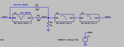
Here is the basic concept.
We started with a Total Harmonic Distortion of 0.017219% (Vout1)
V(out2) is already at 0.000401%.
V(out3) is at 0.000002%
Of course this is idealized, like I said before, the biggest contribution would be the caps here as well as the opamp (obviously).
The beauty of this technique, is that the sine wave coming out of the DAC, from like a PC or DSP, can be precisely tuned at the notch frequency, since we are not interested if we have a perfect 1kHz sine wave (1.05kHz will do fine to measure equipment).
I estimated a notch with a Q of 18, the higher this number is, the better.
Also here the caps have the highest tolerances in practice to get the Q as high as possible.
Although 0.5% is available I think.
0.018% THD is already quite a bit, I just modeled this with some sinewaves, up to the 7th harmonic.
In reality the distortion from the DAC will be much lower, and everything else will scale accordingly.
The notch frequency can be found by using a differential amplifier with the original signal and the signal coming out from the notch.
Most computers are capable of a samplerate of 44.1kHz.
So this means a FFT length of at least 88.2k is needed.
I think that is very doable. Most programs are capable of a FFT length of 256k even.
Attachments
Last edited:
Exactly. BTW, I have followed a more digital route. The output of the (passive) twin T filter is used as input for a feedback loop (via a separate ADC and DAC). The amount of feedback is controlled digitally and updated once per second.Here is the basic concept.
We started with a Total Harmonic Distortion of 0.017219% (Vout1)
V(out2) is already at 0.000401%.
V(out3) is at 0.000002%
Of course this is idealized, like I said before, the biggest contribution would be the caps here as well as the opamp (obviously).
The beauty of this technique, is that the sine wave coming out of the DAC, from like a PC or DSP, can be precisely tuned at the notch frequency, since we are not interested if we have a perfect 1kHz sine wave (1.05kHz will do fine to measure equipment).
Also the DAC frequency is adjusted (also once per second) to stay tuned to the notch frequency.
In this way I could reduce the THD of ten harmonics well below -180dB (noise, hum or spurious 'gras' is of course much higher).
Cheers, E.

That's a very nice an elegant way as well!Exactly. BTW, I have followed a more digital route. The output of the (passive) twin T filter is used as input for a feedback loop (via a separate ADC and DAC). The amount of feedback is controlled digitally and updated once per second.
Also the DAC frequency is adjusted (also once per second) to stay tuned to the notch frequency.
In this way I could reduce the THD of ten harmonics well below -180dB (noise, hum or spurious 'gras' is of course much higher).
Cheers, E.
Makes a lot of sense 🙂
I guess you did the feedback loop with something like mathlab or something?
Or more something like xcos/simulink (labview)?
Mind sharing more information?
The biggest challenge is indeed mostly getting the noise floor down.
At these levels, a lot is gonna depend on a proper PCB design.
Last edited:
@b_force,
With Matlab or so? No, that's way too slow or impossible anyway.
Also the synthesizer, that generate the sine wave and ten harmonics or so, burns a lot of CPU cycles.
It's a new feature of DiAna (programmed in C). This version is still in a beta phase and will be released soon (I hope).
But first I have to finish another challenge: addressing two ASIO drivers within the same program. Why? Because the E1DA Cosmos ADC -for example- has no accompanying DAC. So you have to load one more driver that does support a DAC.
Cheers,
E.
Temperature dependency of what? Twin T filter or harmonic signature of the DAC or both?These techniques usually do not work because of the strong temperature dependency. There is always an imbalance.
Cheers,
E.
I find both a little far fetched.Temperature dependency of what? Twin T filter or harmonic signature of the DAC or both?
Cheers,
E.
Although I give the capacitors and/or the opamps the higher sense of the doubt.
The thermal coupling withing a IC package is pretty decent.
At normal (room) temperatures all is good.
That's true, although I think noise is gonna be a much bigger issue here.@b_force,
Whether far-fetched or not, depends on how much you want to lower the THD measurement floor. If only 20dB, yes, then far-fetched. If 60dB then a lot things get rather critical.
Cheers,
E.
Getting that down by 20dB is quite the challenge.
Every win7+ system has a decent WASAPI UAC2 driver, there should be no reason to be pushed to use ASIO for UAC2 devices anymore. If the device side is not compatible with the strict spects of the MS UAC2 driver, their firmware USB config fields and/or async feedback value should be modified as necessary. Either by the companies using the chip, or pushing the chip vendors (XMOS , Comtrue) to finally do so. Most of the UAC2 ASIO drivers were coded by Thesycon which also delivered the UAC2 driver for MS.addressing two ASIO drivers within the same program. Why? Because the E1DA Cosmos ADC -for example- has no accompanying DAC. So you have to load one more driver that does support a DAC.
There are several open-source device-side implementations which satisfy the MS UAC2 driver, at least two of them being discussed on these forums, the know-how is publicly available. The device will stay fully UAC2 compliant, supported in OSX and linux which have more tolerant UAC2 drivers. WASAPI Eclusive is comparable to ASIO in terms of performance, it can even give the apps access to the PCI device DMA buffer, just like ASIO and linux alsa hw:X (not applicable to USB devices, of course).
Can two ASIO devices be loaded onto the ASIO COM interface? I have not seen anyone doing that but I may be very wrong.
Actually I am using this all the time with a VST host for my guitar and some other instruments, no problemaddressing two ASIO drivers within the same program. Why? Because the E1DA Cosmos ADC -for example- has no accompanying DAC. So you have to load one more driver that does support a DAC.
Cheers,
E.
As a work-around for now, you could also rely on virtual cable or similar, and just route the signals via an host.
Some of those hosts are open source as well, so it might be helpful to poke around the source code or just ask some questions to the creators.
FYI Virtual cable: https://shop.vb-audio.com/en/win-apps/19-hifi-cable-asio-bridge.html?SubmitCurrency=1&id_currency=1 A little tricky to get sorted at first but works pretty well. I have used it to coup[le the QA401 ASIO driver to Praxis, and Win XP audio suite in Win 10. It can be done.
Also Virtin's supports two different ASIO devices as source and destination, another example that it CAN be done. Doing may be a lot of fiddling and possibly coding.
Also Virtin's supports two different ASIO devices as source and destination, another example that it CAN be done. Doing may be a lot of fiddling and possibly coding.
Based on this insightful msg https://www.kvraudio.com/forum/viewtopic.php?p=2303605&sid=2867e65a33cc6fb260a895d552e5558b#p2303605 I looked at the ASIO SDK. The ASIO host library in its API method loadAsioDriver() creates one static driver variable theAsioDriver (defined in asio.cpp) which gets used internally in all ASIO API methods. IF the loadAsioDriver returned the asio driver instance and IF the API let user pass this driver instance to all ASIO methods, instead of using the static instance internally, it would be most likely possible to have multiple drivers instantiated and accessed within one loaded ASIO library.
So each process (having one instance of the loaded library, hence one instance of theAsioDriver structure) can use one different driver, but one process cannot use two drivers. Unless the process uses a modified ASIO library with appropriate changes. There may be some restrictions on distributing the build of the modified ASIO host library, maybe not, no idea.
So each process (having one instance of the loaded library, hence one instance of theAsioDriver structure) can use one different driver, but one process cannot use two drivers. Unless the process uses a modified ASIO library with appropriate changes. There may be some restrictions on distributing the build of the modified ASIO host library, maybe not, no idea.
@ Demian and Pavel,
Of course a single process cannot open two (different) ASIO drivers, but a single program can manage more than one process, each of them accommodating their own ASIO driver. That's what I'm busy with now and I hope it will work that way.
Cheers,
E.
Of course a single process cannot open two (different) ASIO drivers, but a single program can manage more than one process, each of them accommodating their own ASIO driver. That's what I'm busy with now and I hope it will work that way.
Cheers,
E.
A possible complication with multiple ASIO devices might have to do with which asynchronous USB device serves as master clock?
More complicated if the two devices are not running the same clock. For measurement purposes they must use a common clock. The pro interfaces support external master clocks so they can sync. Some (Lynx) have ASRC's on each input BUT those will seriously mess with audio measurements.
Hi Pavel,Based on this insightful msg https://www.kvraudio.com/forum/viewtopic.php?p=2303605&sid=2867e65a33cc6fb260a895d552e5558b#p2303605 {...]
This link also suggests the following solution:
"What you can do is provide multiple 'instances' of callback functions (easy to generate with a template meta program). These functions can then be bound to objects. (or for the sake of simplicity, if you only allow 2 sound cards have BufferSwitch1 and BufferSwitch2 functions and duplicates of all the others you need)."
I'm sort of doing the same thing, that is, starting the main program (instance), which in turn invokes an additional process, which in turn takes care of the second ASIO driver. Preliminary results look promising: the first driver runs as usual and the second driver 'shows activity'. IOW it's not dead. The next step will be to process the data (from the 2nd driver) in an orderly way.
Cheers,
E.
- Home
- Design & Build
- Equipment & Tools
- Low-distortion Audio-range Oscillator