Are the settings the same as they've always been, or have you changed anything such as multi-purpose pin mode?
The only changes were to the buttons and led, done initially when programmed months ago, done nothing since. Led simply to shut off (it annoys me). Buttons to make them all active as inputs. Not using the 1938 in a mode that needs out3/lrclk so the input9 button can work. Has worked just fine for the last 8+ months, now each board (apparently dsp not codec board) is having some sort of failure.
That's a strange one. You don't have some DC on your audio lines or something that might slowly degrade it? Or pulling a high output GPIO directly to gnd? They are not really meant to source current.
Any change to usb in any way, cable, hub, charger, device?
I recently had a problem turned out power was marginal, but had been just enough and a different cable made it unreliable.
Also try adding capacitors across the power lines on the DSP to both filter and reduce chance of brownout - and check any existing ones, I've just remembered that it might have been a failing tantalum cap that didn't help either.
No cable differences or otherwise. A bad tantalum eh? I'll put the scope on the power lines again to be sure.
I wish it was that simple. The three board sets are used in three different ways with three different setups. One for my prototyping, two for two different audio setups.That's a strange one. You don't have some DC on your audio lines or something that might slowly degrade it? Or pulling a high output GPIO directly to gnd? They are not really meant to source current.
Makes me wonder if I got boardsets from a batch that have issues with something on the dsp portion.
Anyone else had the dsp portion just start hanging for no reason after months of use?
Found the issue: The series pass transistor for the 1.2v dvdd supply has died on each unit. The 3.3 volt is seen at the emitter, the 650 mv at the base. Collector is dead.
Anyone know what part was used by them? The schematic leaves a lot to be desired in this regard, there is no useful legend for many things and a few inaccuracies.
Anyone know what part was used by them? The schematic leaves a lot to be desired in this regard, there is no useful legend for many things and a few inaccuracies.
Member
Joined 2018
It seems ordinary PNP transistor. I guess it is used in a feedback loop, so just need focusing on Pc and HFE is enough.
https://ez.analog.com/cfs-filesyste...2.png_2D00_370x480x2.png?_=636991443878121988
https://ez.analog.com/cfs-filesyste...2.png_2D00_370x480x2.png?_=636991443878121988
Yes, know fully well it is a pnp, and a beta of between 100 and 150 aught to about do it. However, the reason for wanting to know what part they used is so I can see if it was marginal in selection in some way.
Member
Joined 2018
Well ADAUA1467 DVDD consumes 940mA@1.2V
This means (3.3V-1.2V)*0.94A = 1.974watts dissipation should be allowed. It seems not enough for that purpose. I have MusicWorks's ADAU1466 board, it also has quite a poor PNP transistor for that section.
This means (3.3V-1.2V)*0.94A = 1.974watts dissipation should be allowed. It seems not enough for that purpose. I have MusicWorks's ADAU1466 board, it also has quite a poor PNP transistor for that section.
Hi Andrea, I'm interested in your work and I would like to have some info directly from you, but unfortunately, your profile isn't public. Could you kindly contact me by PM? Thanking you in advanceearly in August i received the board from China and finally i've been able to program it from Sigma Studio using an utility i developed running on a Arm SBC (Cubieboard with Allwinner A10..)
you can find everything about the experience here on github: GitHub - aventuri/sigma_tcp: a C gateway IP/I2C between Analog Device SigmaStudio and ADAU DSP
if you have questions and issues, let me know here..
in the repo there are the schematics of the board too..
bests
andrea
Antonello
Hi,
I bought this module couple weeks ago:
https://pl.aliexpress.com/item/4001...o2pol&spm=a2g0o.order_list.0.0.21ef1c24wzb7mI
and almost everything was ok until I connected analog inputs that didn't work properly. Input A/B both channels worked poorly, C/D worked only left channel very poorely.
After some research I found out that R88, R90, R92, R94 was 50ohm instead of 6k8 (should have the same value as R77/80/83/86) and IC13 was broken.
I replaced that parts and now the module works ok.
So please be careful starting with this module.
HiI'm using ESP32 to program ADAU1401 over the WiFi. GitHub - hasaranga/SigmaESP32: ADAU1401 Wireless Access using ESP32
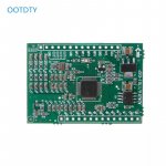
Are you using this board from attached image in your setup?
I'm also using MCUdude's library with esp8266 but had no luck to talk to adau1401 via i2c...
Attachments
Nevermind, it was the code line missing problem, everything working now.Hi
Are you using this board from attached image in your setup?
I'm also using MCUdude's library with esp8266 but had no luck to talk to adau1401 via i2c...
Hi all,
I bought this "ADU1452 CS42448 CODEC Multi-channel Decoding Electronic 4 Frequency Divider Board 6 in 8 out board" thing: https://www.aliexpress.com/item/100..._list.0.0.747d1802iyFZpe&gatewayAdapt=glo2pol
However I cannot get the device to show up on the PC at all in an attempt to install drivers (which ones, I have no idea). Any ideas on where to go from here? Tried different USB cables and ports.
That DSP canot connect directly to PC thru USB. You need the programmer and SIGMASTUDIO to upload the correct project.Hi all,
I bought this "ADU1452 CS42448 CODEC Multi-channel Decoding Electronic 4 Frequency Divider Board 6 in 8 out board" thing: https://www.aliexpress.com/item/100..._list.0.0.747d1802iyFZpe&gatewayAdapt=glo2pol
However I cannot get the device to show up on the PC at all in an attempt to install drivers (which ones, I have no idea). Any ideas on where to go from here? Tried different USB cables and ports.
View attachment 1058581
It's really very straight forward. I am not that tech savvy and managed to make it work.Aha that makes sense, not sure why I missed that.
Hi all, I've got the ADAU1452 board as in the photos from fackamoto this morning, and I can get sound in and out of the DSP with no problems. I can also run the 1kHz test program when the LED is blue, but I can't get it to run my program. Am I missing something with the LED colour and the three switches? I'm trying to just run the reverb block in SigmaStudio and it says it's compiling and downloading correctly, but it's not doing anything. Ii'm getting the clean signal with the LED red, 1kHz sine wave when it's blue, and no sound when it's green.
Have the same board, ADAU1452_DSP with CS42448 piggyback, this board does not integrate the MCU_STM32F103C8T6. Also purchased the programmer from the same vendor Nvarcher.That DSP canot connect directly to PC thru USB. You need the programmer and SIGMASTUDIO to upload the correct project.
Was not able to connect with programmer using the "SPI" pins. I've instantiated the 1452 from the SigmaStudio and tried to "read all registers" with no reaction. Is there a walkthrough for this board somewhere?
Will appreciate help.
- Home
- Source & Line
- Digital Line Level
- low cost ADAU1452 China board...