Yes, you should check all of the other components. Transistors can go O/C and testing them in circuit is not always definitive. I would be inclined to replace them all anyway. If something nasty has happened, then transistors which are still apparently operating may have seen some partial overload and have reduced life (walking wounded). The resistors can be checked once the trannys are out, but you can still lift one end to be certain. All effort into evaluating what went wrong and who is alive/dead on your board will pay off. It would not be worth it to put new trannys in if a resistor was shorted, for example.I have today removed the twoTIP3055s and the DBT is now out. I don't have any spares so I will source some more. I found the empty bag i originally got in 2006 and I see I got them from ebay 🙁. I will be sourcing them from RS or Mouser or similar. I will also check that the other components are ok and the values are correct.
'wise decision, since few of us have instruments or the bits and pieces necessary to make one that's capable of checking power transistors under working conditions. Ebay components aren't all from China though and there are traders of original parts out there too. The problems being that they probably want a lot more money for genuine NOS products and it's difficult to identify what are to some degree legitimate copies, what are actually fakes and re-numbered types, Industrial or military versions, 2nd source etc. They could even be reject or just excess stocks of unwanted product, from anywhere around the globe.
I guess the obvious flaw in my argument is that being about the cheapest TO3 transistor available, who'd be bothered to make fakes of 2N3055? Well, if I had a barrel of unknown TO3 junk transistors lying around, even I think I know just what to do and who to then offer them to.
I guess the obvious flaw in my argument is that being about the cheapest TO3 transistor available, who'd be bothered to make fakes of 2N3055? Well, if I had a barrel of unknown TO3 junk transistors lying around, even I think I know just what to do and who to then offer them to.
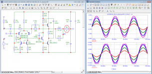
Guys, I made some changes to my amp. What do you think?
I changed the input capacitor which was 0.47uF polyester for two electrolytic series 10uF = 5uF capacitor (bipolar). C4 and C7.
And at the output, I put another capacitor in parallel of 4,700uF. C6.


I changed the input capacitor which was 0.47uF polyester for two electrolytic series 10uF = 5uF capacitor (bipolar). C4 and C7.
And at the output, I put another capacitor in parallel of 4,700uF. C6.
I would not have thought it necessary to use two electrolytics back to back in the input stage as the base of the PNP is sitting at around half supply, so biases the electrolytic the right way (positive to the base, negative to input, that is).
You would only do this normally if an electrolytic works around zero volts or ac. even then I tend to use non-polarised caps for input connections and while I think 0.47uF was too small, probably 1 or 2.2 uF would be adequate.
Noise at low frequencies can increase with a high impedance so a larger capacitor is preferable, but VLF noise is not audible.
You should see a better bass response with the larger output capacitor.
I have not considered the time constants interacting but I would simulate the overall result to check. It's probably better to make the input limit the response rather than the feedback decoupling capacitor so that the voltage on the decoupler is minimised, reducing distortion it might cause.
Thanks for the answer. Would it be better to put a 2.2uF polyester capacitor at the input?I would not have thought it necessary to use two electrolytics back to back in the input stage as the base of the PNP is sitting at around half supply, so biases the electrolytic the right way (positive to the base, negative to input, that is).
You would only do this normally if an electrolytic works around zero volts or ac. even then I tend to use non-polarised caps for input connections and while I think 0.47uF was too small, probably 1 or 2.2 uF would be adequate.
Noise at low frequencies can increase with a high impedance so a larger capacitor is preferable, but VLF noise is not audible.
You should see a better bass response with the larger output capacitor.
I have not considered the time constants interacting but I would simulate the overall result to check. It's probably better to make the input limit the response rather than the feedback decoupling capacitor so that the voltage on the decoupler is minimised, reducing distortion it might cause.
Member
Joined 2009
Paid Member
Higher voltage rating means thicker interface on electrodes and usually that's better quality overall. Only reason to choose lower voltage rating is size and cost
Yes, a polyester or polycarb capacitor should have lower noise than an electrolytic.
I'd also agree with increasing the bootstrap and feedback decoupling capacitors.
Time constant of the input stage: depends on gain of 2SA992. Typical min. 200 gives a min. value of approx. 220x200=44k.
parallel load of bias resistors = 47k, total approx. 23k. 1uF x23k=23ms. Rather high, depends on what you want the amp. LF performance to be.
Prob. 2.2uF better. Could be better if your A992 device gain is higher (typ. 500), but that depends.
Bootstrap probably more important to increase. Capacitor sees 100 // 220 so at 68 ohms or so 330uF x 68 is 22mS and somewhat high, and not so dependent on the gain of the transistors. 1mF would be my recommendation too. I would also increase the decoupling capacitor and try to make sure the input cap. limits the roll-off as far as the input/drive stages are concerned.
Output cap can be larger still if you like. 10mF or 22mF for better low frequency square wave performance. Depends on your speakers too. Many people thought 2.2mF Ok back in the 60's, but LF performance is definitely inferior.

Thanks!!!Yes, a polyester or polycarb capacitor should have lower noise than an electrolytic.
I'd also agree with increasing the bootstrap and feedback decoupling capacitors.
Time constant of the input stage: depends on gain of 2SA992. Typical min. 200 gives a min. value of approx. 220x200=44k.
parallel load of bias resistors = 47k, total approx. 23k. 1uF x23k=23ms. Rather high, depends on what you want the amp. LF performance to be.
Prob. 2.2uF better. Could be better if your A992 device gain is higher (typ. 500), but that depends.
Bootstrap probably more important to increase. Capacitor sees 100 // 220 so at 68 ohms or so 330uF x 68 is 22mS and somewhat high, and not so dependent on the gain of the transistors. 1mF would be my recommendation too. I would also increase the decoupling capacitor and try to make sure the input cap. limits the roll-off as far as the input/drive stages are concerned.
Output cap can be larger still if you like. 10mF or 22mF for better low frequency square wave performance. Depends on your speakers too. Many people thought 2.2mF Ok back in the 60's, but LF performance is definitely inferior.
Hi guys, my videos showing my amplifier and tests are on a new youtube channel: "Electrônica Tiago Sierra".
Here's the plylist with the videos:
https://www.youtube.com/playlist?list=PLceAdLTPocSHFkuiKAzEND4Blkb3-oGuQ
PDF circuit diagram:
https://drive.google.com/drive/folders/1hqNqf1LpdyNb26nMPSwo5KOk3z-7M26V
Here's the plylist with the videos:
https://www.youtube.com/playlist?list=PLceAdLTPocSHFkuiKAzEND4Blkb3-oGuQ
PDF circuit diagram:
https://drive.google.com/drive/folders/1hqNqf1LpdyNb26nMPSwo5KOk3z-7M26V
I would like to improve/upgrade my chinese made "JLH 1969". It was sold as "2017 18W model" with MJ15025 & MJ15024 transistors.
It does sound pretty good already, but I would like to upgrade components to get as good sound as possible. Since it is chinese made, I'm sure there is room for improvements.

For starters, I have bought new output capacitors (Mundorf MLytic AG glue on 2200 uF 63VDC 125C 2pin). Am I correct in assuming that they should replace these?

The blue ones are labelled as 1500 uF, but I was advised to get 2200 uF instead.
What would be the next thing to replace? I assume the transistors are counterfeit, so I guess that would be a place to start? Should I simply get legit versions of the same MJ15025/MJ15024 models, or would it be better to replace them with something else?
The speakers I am driving are Troels Gravesen TQWT (95 dB): http://www.troelsgravesen.dk/JA8008.htm
Thanks!
It does sound pretty good already, but I would like to upgrade components to get as good sound as possible. Since it is chinese made, I'm sure there is room for improvements.
For starters, I have bought new output capacitors (Mundorf MLytic AG glue on 2200 uF 63VDC 125C 2pin). Am I correct in assuming that they should replace these?
The blue ones are labelled as 1500 uF, but I was advised to get 2200 uF instead.
What would be the next thing to replace? I assume the transistors are counterfeit, so I guess that would be a place to start? Should I simply get legit versions of the same MJ15025/MJ15024 models, or would it be better to replace them with something else?
The speakers I am driving are Troels Gravesen TQWT (95 dB): http://www.troelsgravesen.dk/JA8008.htm
Thanks!
https://sound-au.com/tcaas/index-1.htmI would like to improve/upgrade my chinese made "JLH 1969". It was sold as "2017 18W model" with MJ15025 & MJ15024 transistors.
It does sound pretty good already, but I would like to upgrade components to get as good sound as possible. Since it is chinese made, I'm sure there is room for improvements.
View attachment 1057713
For starters, I have bought new output capacitors (Mundorf MLytic AG glue on 2200 uF 63VDC 125C 2pin). Am I correct in assuming that they should replace these?
View attachment 1057715
The blue ones are labelled as 1500 uF, but I was advised to get 2200 uF instead.
What would be the next thing to replace? I assume the transistors are counterfeit, so I guess that would be a place to start? Should I simply get legit versions of the same MJ15025/MJ15024 models, or would it be better to replace them with something else?
The speakers I am driving are Troels Gravesen TQWT (95 dB): http://www.troelsgravesen.dk/JA8008.htm
Thanks!
Dreew: What do you think about this one?
https://www.diyaudio.com/community/threads/jlh-1969-explanation.331158/post-6404128
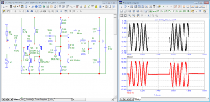
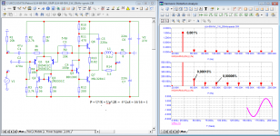
I propose these changes
https://www.diyaudio.com/community/threads/jlh-1969-explanation.331158/post-6404128
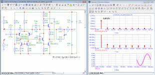
I propose these changes
Attachments
-
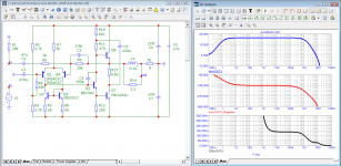 JLH-69_INV-GMP_Bode.png31.7 KB · Views: 288
 -
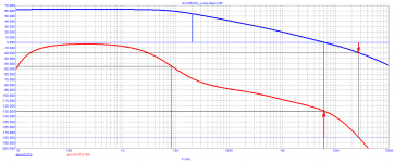 JLH-69_INV-GMP_Loop-Gain.png9.5 KB · Views: 267
 -
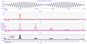
 JLH-69_INV-GMP_10kHz-dist.png33.6 KB · Views: 215
 -
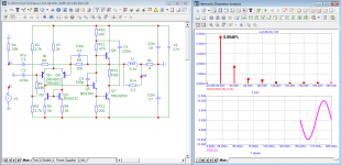 JLH-69_INV-GMP_20kHz-spectr.png30.9 KB · Views: 221
 -
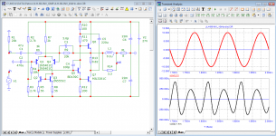
 JLH-69_INV-GMP_RL=4_20kHz-cliping.png37.8 KB · Views: 208
 -
 JLH-69_INV-GMP_20Hz-burst.png32.9 KB · Views: 293
NOT more than 6-8 watts/ch in class A. Small heatsink area.chinese made "JLH 1969". It was sold as "2017 18W model" with MJ15025 & MJ15024 transistors
Here's a new idea for an improved version from 1996, I haven't tested it yet but I will very soon, it's similar to my previous version with jfet and depletion mosfet in CCS. CCS are now cascades with a bias multiplier by Walt Jung's article published in audioXpress 4/09.
https://www.diyaudio.com/community/threads/jlh-10-watt-class-a-amplifier.3075/page-346#post-6299800
https://www.diyaudio.com/community/threads/jlh-10-watt-class-a-amplifier.3075/page-346#post-6299800
Attachments
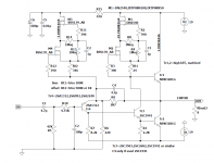
In general a JFET current source is much quieter than one using depletion mode MOSFETs.
Unless you need more voltage than 50V, I personally would use a 2SK208GR or 2SK209GR cascoded by a 2SK209BL to make up a 3mA CCS.
Fine adjustment with a single source resistor for the (lower) GR-grade JFET.
And just use multiple in parallel if I need more current.

Patrick
Unless you need more voltage than 50V, I personally would use a 2SK208GR or 2SK209GR cascoded by a 2SK209BL to make up a 3mA CCS.
Fine adjustment with a single source resistor for the (lower) GR-grade JFET.
And just use multiple in parallel if I need more current.
Patrick
Last edited:
- Home
- Amplifiers
- Solid State
- JLH 10 Watt class A amplifier