You're fine. You won't be able to measure or hear any difference between channels.Hi, thanks for your reply.
Actually, I have 0.4V differences between both power supply i could not fixed but i am not sure if it as impact.
And for quiescent current I measured the voltage accross the R10 resistor (0.330ohm) but as I could not be 100% sure of its value, the quiescent current could have 0.1 A difference (at maximum)
Replying to my own thread...View attachment 1023598
I think if I just use a pair of series caps, then the two CC sources will pull the centre tap up via R11 and R12. So I'll either balance them with a resistor between centre tap and -v rail, or double the value of R11 and 12 and take them to -ve rather than gnd.
However, from what you say (quoted above) all works fine without modifying the circuit or adding the balancing resistor?
I'm away from home as we speak, and itching to get back to the veroboard...
I think this might be problematic. Returning the speaker to a 'ground' that's just AC coupled, a signal will modulate the CCS's and the input ground. THis could end badly.
So I tried a sim of AC coupling the speaker and fb cap (C4 in original) to PSU -v, the CCS resistors increased in valu and taken to the same point, and a new pair of resistors and a cap to create VCC/2 for the inputi This seems to work.
Any thoughts?
Attachments
417 pages! And I read them all...Took a few nights! I need a reality check. I'm intrigued with anything HiFi Amplification. Many years ago I built dozens of Heathkits, Eico kits, Knight Kits and especially Dynaco Kits.....Last year, during lock down I built a VTA/Bob Latino ST120 Dynaco clone. A couple months ago I dived into a First Watt F5v2 that someone else cobbled together and with Randy's (First Watt Guru) help, I replaced the power supply, added VU meters and a few other accoutrements. A week ago I built a K-12G four tube amplifier and just this week built a "plug and play" ICE Class-D amplifier. I got more amplifiers now than I know what to do with. (You can read all about these adventures here... wwwrvbprecision.com)
As you can see, I'm an "assembler" ....not a technician. I do not posses the knowledge to build an amplifier or power supply from scratch....I'm a very good solderer and I can follow directions!
Now I discover the JLH 1969 and I'm smitten. This might be a good, inexpensive way, to learn more about amplification circuitry.
Reality check......What is the opinion of the cheap Chinese 1969 kits that you find everywhere?
https://www.ebay.com/sch/i.html?_from=R40&_trksid=m570.l1313&_nkw=393408084058&_sacat=0
If one was to purchase two of these module kits, a couple big heat sinks and build some type of cabinet, , what is the easiest way to power such an amplifier.
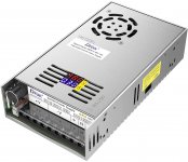
Would buying a simple Buck Converter switching power supply like from "Mean Well" be a good idea?
Is there a COMPLETE power supply kit available that someone with my knowledge level could build?
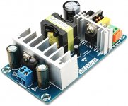
What is the opinion of this type of PS...
https://www.amazon.com/gp/product/B01EE4UX18/ref=ox_sc_act_title_3?smid=A30Y6WWS77DGEW&psc=1
Can these amps run off a simple transformer?
Any help as I start this adventure would be welcome....Thanks in advance
As you can see, I'm an "assembler" ....not a technician. I do not posses the knowledge to build an amplifier or power supply from scratch....I'm a very good solderer and I can follow directions!
Now I discover the JLH 1969 and I'm smitten. This might be a good, inexpensive way, to learn more about amplification circuitry.
Reality check......What is the opinion of the cheap Chinese 1969 kits that you find everywhere?
https://www.ebay.com/sch/i.html?_from=R40&_trksid=m570.l1313&_nkw=393408084058&_sacat=0
If one was to purchase two of these module kits, a couple big heat sinks and build some type of cabinet, , what is the easiest way to power such an amplifier.
Would buying a simple Buck Converter switching power supply like from "Mean Well" be a good idea?
Is there a COMPLETE power supply kit available that someone with my knowledge level could build?
What is the opinion of this type of PS...
https://www.amazon.com/gp/product/B01EE4UX18/ref=ox_sc_act_title_3?smid=A30Y6WWS77DGEW&psc=1
Can these amps run off a simple transformer?
Any help as I start this adventure would be welcome....Thanks in advance
Attachments
Hah, I too read them all and tried not to get sidetracked.
A few here have built various eBay kits and as far as I recall noones suffered the release of magic smoke. I'd be skeptical of the thermal efficiency with that rather flimsy bracket. Better to mount the transistors directly onto the heatsink, there's a lot of heat to get rid of. Conrad do a very neat solution for to3 cases: http://www.conradheatsinks.com/products/single_f.html
You could use these with the eBay boards and recycle their angle. I've used these heatsinks, proper quality they are.
I'm using Meanwell smps for a class d amplifier with no issues and plan to use them with a jlh. Linear transformer and caps are bulky and expensive, and the series resistors or regulators chuck out still more heat that we don't need. A few forum members have used smps with jlh. I see no reason not to. Someone mentioned that if you're using two you might need to beware of beat frequency. I haven't had a problem with my two Meanwells.
Yes you can run any number of them from a single transformer. Just needs to be powerful enough. Ah... you said "simple" not "single". Yes, but you need a lot of capacitance and ideally some RC filtering. https://www.duncanamps.com/psud2/ is a very useful tool. Hours of fun, and you'll always come to the conclusion that there's no such thing as too many capacitors.
for me, the best way for the JLH is to buy an old sound amplifier (type cerwin vega) with large heatsinks provided for TO3 and plenty of space inside.
I tried all the possible configurations and (for me) the best configuration remains a classic and well-sized power supply transformer and a Pi power supply with a first stage of reasonably sized capacitors (10kuF) followed by a resistor (between 0.47 and 1 ohm) and behind, the big artillery (between 100 and 300KuF).
I arrived there after many tests and reading in particular on the work of Jean Hiraga on "Le monstre". (8w,20w,30w)
This is "my" opinion and I am not a reference.
after if you have read the whole thread, you should know that the first price Chinese kits are very good, that it is necessary to change all the transistors by authentic ones, that it is not necessary to put power transistors super fast, that the pairing of these is important.
it's a simple amp, but simple doesn't mean easy, it just means it's easy to operate, but to get the best out of it takes hours and hours of work and testing.
Hello, guys, I'm doing other tests on my JLH 1969 (10W). Putting signal to test the output. Maximum signal input is 524mV. Maximum output 6.45V. Test done with 1kHz.
In this video I show tests with other frequencies, to see the wave signal.
Input signal = 480mV
Specifications:
JLH 1969 (10W) monoblock amplifier.
I set up 2 amplifiers to make stereo.
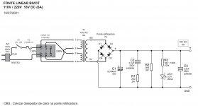
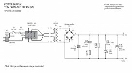
Power supply:
Transformer: 110V / 220V (60Hz) / 0+18V AC 6A
Rectifier bridge: 8A
Capacitor: 22,000uF (63V)
Power on amplifier board: 18V DC
Bias (I.Q.) = 2A
Distortion-free maximum power (1kHz) = 7W rms (per channel)
Distortion-free maximum signal input (1kHz) = 524mV (-3.5dB)
Maximum undistorted signal output (1kHz) = 6.45V
Speakers = 6 ohms
Temperature in components:
Amplifier on for 2 hours.
Ambient temperature = 25°C
Transistor 2SC5200 = 55ºC
2SC5200 heat sink = 40°C
Rectifier bridge = 51°C
Rectifier bridge heat sink = 39°C
Transformer temperature = 40°C
Playlist videos showing the amplifier and tests:
https://youtube.com/playlist?list=PLfaWCRXEiDtwbxh9Z5zZtqOg1GG5cesc6
Circuit diagram PDF:
https://drive.google.com/drive/folders/1hqNqf1LpdyNb26nMPSwo5KOk3z-7M26V
Tiago Sierra
In this video I show tests with other frequencies, to see the wave signal.
Input signal = 480mV
Specifications:
JLH 1969 (10W) monoblock amplifier.
I set up 2 amplifiers to make stereo.
Power supply:
Transformer: 110V / 220V (60Hz) / 0+18V AC 6A
Rectifier bridge: 8A
Capacitor: 22,000uF (63V)
Power on amplifier board: 18V DC
Bias (I.Q.) = 2A
Distortion-free maximum power (1kHz) = 7W rms (per channel)
Distortion-free maximum signal input (1kHz) = 524mV (-3.5dB)
Maximum undistorted signal output (1kHz) = 6.45V
Speakers = 6 ohms
Temperature in components:
Amplifier on for 2 hours.
Ambient temperature = 25°C
Transistor 2SC5200 = 55ºC
2SC5200 heat sink = 40°C
Rectifier bridge = 51°C
Rectifier bridge heat sink = 39°C
Transformer temperature = 40°C
Playlist videos showing the amplifier and tests:
https://youtube.com/playlist?list=PLfaWCRXEiDtwbxh9Z5zZtqOg1GG5cesc6
Circuit diagram PDF:
https://drive.google.com/drive/folders/1hqNqf1LpdyNb26nMPSwo5KOk3z-7M26V
Tiago Sierra
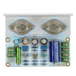
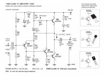
My circuit. Monoblock.
JLH 1969 (10W) Class A.
Playlist videos showing the amplifier and tests:
https://youtube.com/playlist?list=PLfaWCRXEiDtwbxh9Z5zZtqOg1GG5cesc6
JLH 1969 (10W) Class A.
Playlist videos showing the amplifier and tests:
https://youtube.com/playlist?list=PLfaWCRXEiDtwbxh9Z5zZtqOg1GG5cesc6
Attachments
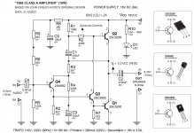
UPDATE CIRCUIT. OBS.My circuit. Monoblock.
JLH 1969 (10W) Class A.
Playlist videos showing the amplifier and tests:
https://youtube.com/playlist?list=PLfaWCRXEiDtwbxh9Z5zZtqOg1GG5cesc6
Attachments

Hi Gary, I assembled the PCB myself, soldered the components on a board with holes. I used 0.3mm and 1mm cables.sierratds, what pcb did you use for the JLH 1969 amp channels?
See the vídeo 4:
Hello Friends, prasi,gerbers and pdfs
Thank you for the discussion and for sharing the files. I have decided to build this as my next project.
Before I move further, may I ask if there is any revision for this board, or is this the latest one? Thank you.
Anyone hear from Nigel Pearson?
I contacted him some time ago to find out if he was okay but no response.
I contacted him some time ago to find out if he was okay but no response.
Not sure if i should start another thread or post on here. Some years ago I built a JLH 10w using pcb's supplied by Siliconray. I used the amp on an off and then lent it to a friend. Whilst with him the L channel stopped working. I have now had time ot look at it and there is nothing obvious like burnt components.
With a DBT in the power line a 60w bulb shines very brightly. It is not possible to get any readings from any of the components. I have fiddled with the bias pots to see if this made any difference but sadly no. Is it a case of pulling all components and testing each one?
The power transistors are TIP3055.
Yes.Hello, does the power supply work as it should without load?
I never managed to get the siliconray JLH to work properly, it oscillated so easily depending on the load and very sensitive to output devices, I ended up giving up.
When they worked, I didn't like what came out of them, I had no regrets about giving them up.
When they worked, I didn't like what came out of them, I had no regrets about giving them up.
I have today removed the twoTIP3055s and the DBT is now out. I don't have any spares so I will source some more. I found the empty bag i originally got in 2006 and I see I got them from ebay 🙁. I will be sourcing them from RS or Mouser or similar. I will also check that the other components are ok and the values are correct.
- Home
- Amplifiers
- Solid State
- JLH 10 Watt class A amplifier