Thx, now I get it u meant a prism, that's good because its a lot easier to build then a trapezoid but that will increase the volume of the midrange by a lot like 2x-3xI really like your skills and approach, Alex! I wish that some of my kids would share my hifi interest...
I forgot to add this pic of how to make mid box
View attachment 1045807
You can naturally make the box more shallow and less volume. But large volume is not an issue, because you are anyway highpassing the mid. above it's Fs. Smaller box will have more internal reflections/modes in it's passband.
http://www.mh-audio.nl/Acoustics/SG.html
works with small dimensions! Lowest three /axial modes are worst
works with small dimensions! Lowest three /axial modes are worst
Sorry for jumping around, busy day...
Making the side opposing the driver (depth) in it's box to "appear" has most benefit. The driver is in the middle of hor and vert modes, so at minimum pressure!
Making the side opposing the driver (depth) in it's box to "appear" has most benefit. The driver is in the middle of hor and vert modes, so at minimum pressure!
Excuse me can u rephrase that for me pls I am a bit lost in translation.Making the side opposing the driver (depth) in it's box to "appear" has most benefit. The driver is in the middle of hor and vert modes, so at minimum pressure!
u mean its a good idea to center the side woofers horizontal and vertically so there in the middle?
"to disappear" Sorry for my mistake. Backwave from the opposing wall of the box hits the cone hard and interferes, causing a peak/dip in response. Eliminating this (making it disappear) is the purpose of box stuffing and other tricks like making the depth "infinite" somehow.
https://www.diyaudio.com/community/...e-for-completely-supressing-back-wave.216662/
Placing woofers just in middle of height (or any dimension) makes them prone to 2nd order mode which has maximum at half of the length, it just has a bit lower pressure/amplitude.
http://www.acousticfrontiers.com/room-modes-101/
Last edited:
I own a pair of Kef R3s and have explored what could be done with the drivers should I be so crazy as to cannibalize them. Here is a zip of a Vituix sim of a KEF Blade 2, similar to the figure in the OPs post #8. It uses directivity posted by amir in his KEF R3 review. The Vituix simulation using the KEF directivity and diffraction tool created directivity for 5" woofers - Faital 5FE120 shows the power response and predicted in room response for the blade-like configuration. This sim is easily modded into a sim for the W-Coax-W which has equally nice power response and PIR and uses only 2 woofers. But if using only 2 woofers, you might prefer slightly larger ones - like the Purifis but perhaps not so expensive
Attachments

Vivid audio and Estelon speakers get nice reviews with ony two woofers per speaker, down low and xo 2-300Hz...
These are passive speakers, woofers parallel, impedance dropping below 2R
https://www.stereophile.com/content/vivid-kaya-45-loudspeaker
https://www.stereophile.com/content/vivid-audio-giya-g1-spirit-loudspeaker
https://www.stereophile.com/content/estelon-forza-loudspeaker
These are passive speakers, woofers parallel, impedance dropping below 2R
https://www.stereophile.com/content/vivid-kaya-45-loudspeaker
https://www.stereophile.com/content/vivid-audio-giya-g1-spirit-loudspeaker
https://www.stereophile.com/content/estelon-forza-loudspeaker
Last edited:
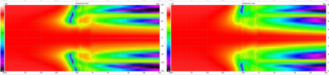
I have attached vituix screenshots from my simulations. The top one is the W-Coax-W simulation. It includes side drivers that have been muted. When unmuted, a cardioid response is enabled that extends directivity control down to about 150 Hz. The lower screenshot is the blade-like configuration. It has a small dip in the power response and PIR near crossover to the woofers which is reduced with some overlap between the coax and the woofers. Interesting horizontal yellow bands in the polar maps likely have something to do with the dual opposed side mounted woofer configuration - Ive never seen them with other configurations. Both these simulations receive a predicted preference score with sub of >10 in Vituix.
Attachments
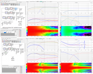
^Supercardioid 200-500Hz
All in all excellent performance! And in-room, as room response closed box woofers work even better/lower.
nc or Alex, can you modify the sim to a pair of opposed woofers at 1/3 height of tower? I can't use VCAD...
All in all excellent performance! And in-room, as room response closed box woofers work even better/lower.
nc or Alex, can you modify the sim to a pair of opposed woofers at 1/3 height of tower? I can't use VCAD...
Still learning how to use vcad, I ll try after work but never worked with anything else then enclosure tool, a bit baffle and very basic crossover 😛nc or Alex, can you modify the sim to a pair of opposed woofers at 1/3 height of tower? I can't use VCAD...
well i am playing with the position but i am not sure if i am doing it right.
i thought the position would be relativ to kefr3 if it is at 0,0,0.
so x value represents from a front view position left(-) or right+(),
y height and z depth?
so i removed 2 woofers gave them x=110/-110, y=-300, z=180


i thought the position would be relativ to kefr3 if it is at 0,0,0.
so x value represents from a front view position left(-) or right+(),
y height and z depth?
so i removed 2 woofers gave them x=110/-110, y=-300, z=180
Attachments
yes to xyz directions. note positive Z is behind 0,0,0
0,0,0 is indeed where the coax should be
why do you have the woofers at Z=180? I would put them on the baffle at Z=0
and you have both woofers at the same Y??? perhaps one should be Y=+300 and the other Y = -300?
also drivers can have a rotation, R = +/- 90 if on the sides. If you started from my zip, you may have to set R=0 for the surviving woofers
and a tilt, T
you have a typo in the X of D4, I hope it wasn't mine to begin with...
right click on a blank portion of the schematic and select "driver layout" and Vituix will show you driver locations
It might be, something doesn't look quite right here but it's hard to tell from the image. Looks like z depth of 3mm on one woofer.you have a typo in the X of D4, I hope it wasn't mine to begin with...
Hello,
I may have missed a few of your recent posts in the other thread exploring ideal cabinets shapes to mitigate diffraction.
How thick and wide is the baffle? Is the side bevel 45 degrees? And radius of the upper panel?
best regards,
Thanh
I may have missed a few of your recent posts in the other thread exploring ideal cabinets shapes to mitigate diffraction.
How thick and wide is the baffle? Is the side bevel 45 degrees? And radius of the upper panel?
best regards,
Thanh
I haven't posted this one before and I haven't simulated it yet either. Fusion crashed before I saved this as anything other than a screenshot and I can't remember all the dimensions.Hello,
I may have missed a few of your recent posts in the other thread exploring ideal cabinets shapes to mitigate diffraction.
How thick and wide is the baffle? Is the side bevel 45 degrees? And radius of the upper panel?
best regards,
Thanh
The woofer circles are 175mm diameter, and the side chamfers were based on a ratio of 1.66:1. That produces a 30 degree bevel. The top radius I'm not sure I will have to draw it again.
Short answer, the more the construct (enclosure and drivers included) resembles a sphere the less diffraction. Big drivers means big sphere, big roundovers / slants.Hello,
I may have missed a few of your recent posts in the other thread exploring ideal cabinets shapes to mitigate diffraction.
How thick and wide is the baffle? Is the side bevel 45 degrees? And radius of the upper panel?
best regards,
Thanh
Anything that is not a sphere will have some diffraction and shape determines which direction it shows up. Main thing is the first edge (baffle) makes the most of it and secondary diffraction on the baffle (and behind the baffle, back of the construct) still affects they just make much less effect as the sound is already attenuated and distributed by the first.
well, they should be same height because atm i wanted to test the two opposing wofers which are lower then Coax and on the sidesyes to xyz directions. note positive Z is behind 0,0,0
0,0,0 is indeed where the coax should be
why do you have the woofers at Z=180? I would put them on the baffle at Z=0
and you have both woofers at the same Y??? perhaps one should be Y=+300 and the other Y = -300?
What is the thought process with this idea? Considering mid enclosure, with low pass filter, it might be possible to have the first mode above the pass band alltogether making opposite case.... Smaller box will have more internal reflections/modes in it's passband.
Example 8" driver with 9cm depth and crossover around 1.5kHz, mounted front of baffle the internal cavity could be made as shallow as perhaps 7cm making first mode about ~2.5kHz, or ~2kHz if considering 9cm distance between the cone and back wall. No modes on pass band with this dimension.
Bigger box would have modes lower in frequency but as you described they could be effectively tamed with damping. If there is problems it is the lowest mode, or two, what ever those are.
- Home
- Loudspeakers
- Multi-Way
- 3-way floorstanding with KEF coax (active)