You can not know the effect without some modeling in some specific software. I'd be looking at what kef did........
Would you change the position of the woofers? decreasing the space between them maybe?
Is the bracing enough?
Find a way to connect front and back baffle. Few struts to connect them will do the job. The way you have it now - they are supported where they need it the least, at corners. You need to connect opposed baffles at spots that are at the middle of the baffle width.
Similar to this:
https://www.audiosciencereview.com/forum/index.php?attachments/img_20211009_162418-jpg.161467/
There are also large unsupported surfaces on sides.
Last edited:

The Module will be in speakers, a separate chamber will be build in the back at the bottom, as u can see in the 3d modelThat was my 'pro' setup for a few months!
Eventually, I put it in a metal box. with a laser-cut top.
View attachment 1053299
Is the fa123 going into the speaker or an external box? The "bud industries ac-411" fits it if you go that route.
The hypex software is for sure clunky.
This image gives a good indication of the relative merits of different bracing on flat panels, the full lengthwise brace being the most effective of the options shown.
When you tie the brace into multiple panels like a dadoed window brace it becomes significantly better. Predicting that needs much more complicated equations or modelling.

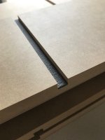
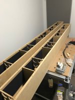
In long tall structures window braces can quite effective. Like in the images attached, I did a bit of constrained damping in the channel with some bitumen type material and flexible glue.
When you tie the brace into multiple panels like a dadoed window brace it becomes significantly better. Predicting that needs much more complicated equations or modelling.
In long tall structures window braces can quite effective. Like in the images attached, I did a bit of constrained damping in the channel with some bitumen type material and flexible glue.
Attachments
I'd consider braces with smaller round openings. The idea is to connect opposing walls and connecting walls both at the same time. At an height of 1100mm I'd add at least one more brace. And how are you going to connect the woofer magnet assemblies back to back?
@woofer spacing: I'd take the profit of spreading them wide apart. That way the system supresses vertical standing waves in your room a bit more than with close spacing. The KEF Muon and a lot of other systems use that approach.
@woofer spacing: I'd take the profit of spreading them wide apart. That way the system supresses vertical standing waves in your room a bit more than with close spacing. The KEF Muon and a lot of other systems use that approach.
According to this photo the spacing between the edge of the membran should be 0,94x the diameter. so in my situation it should be around 15,5cm
right now I am having 20,4cm
i wont 😀...
And how are you going to connect the woofer magnet assemblies back to back?
I thought about one bracing from bottom to top and then connect everything to that
Spacing is probably with wavelength, I suspect all five drivers are about 1/4wl away from eachother at crossover frequency. For 200Hz this would be roughly 40cm. Or conversely, if your spacing is something the crossover frequency is best put abput wavelenght 4x the distance from mid to woofer, or from woofer to woofer.
There is opportunity to affect pattern with this driver configuration, perhaps they do but I suspect the blade is just ment to be a point source with very low diffraction, hence woofer are not on front and not on the mid elevation but above and below.
There is opportunity to affect pattern with this driver configuration, perhaps they do but I suspect the blade is just ment to be a point source with very low diffraction, hence woofer are not on front and not on the mid elevation but above and below.
Very high technology, nice. This one has bit different spacings / locations for woofers that the blade. Hard to tell why, probably optimized with measurements for nice polar pattern, or any other reason hard to speculate from pictures only 🙂 is there klippel set available for the blade or this new one? would be interesting and fun to speculate on 😀
Here is their white paper.Very high technology, nice. This one has bit different spacings / locations for woofers that the blade. Hard to tell why, probably optimized with measurements for nice polar pattern, or any other reason hard to speculate from pictures only 🙂 is there klippel set available for the blade or this new one? would be interesting and fun to speculate on 😀
At the end is the spinorama. 😀
https://us.kef.com/pub/media/ls60-content/LS60W_WP.pdf
Very very high tech, no BS speaker, and very cool to have a public paper like that. Thanks linking it! There is lot of reference in that paper for DIY folk as well as other companies to follow. Exanple of how to push development forward and be honest with it.
Indeed factor spacing from diameter is 0,77 vs. 0,94 from Blade.Very high technology, nice. This one has bit different spacings / locations for woofers that the blade.
i received the Ikea baskets and they are quite a bit smaller then they should be, they only have 1,85+0,15L(cutout)=2.0L
is this a problem or should I add some volume by distance rings (0,25Liter each 19mm step)
is this a problem or should I add some volume by distance rings (0,25Liter each 19mm step)
where distance matters is when there is a tweeter in between them and you are doing the crossover....
or if you plot the vertical directivity. On axis won't change but off axis vertically definitely will
or if you plot the vertical directivity. On axis won't change but off axis vertically definitely will
In all three images the step between the drivers is 210mm and would explain why they look very similar. getting Vituix to put the drivers where you want in a baffle sim can be tricky.I tryed to model the spacing between woofers, seems like it doesnt really care that much
that is not correct, i moved them manually.In all three images the step between the drivers is 210mm and would explain why they look very similar. getting Vituix to put the drivers where you want in a baffle sim can be tricky.
I meant it as a question to check if you had, but didn't write it very well.that is not correct, i moved them manually.
It is more obvious when made into a gif
- Home
- Loudspeakers
- Multi-Way
- 3-way floorstanding with KEF coax (active)