Maybe an idea before its time? Now it makes total sense to maximise the efficiency of the device, with every unused watt saved being a triumph.
A few years ago, no one would have liked the idea of a car that has an engine that stops at traffic lights, but now it is normal. Why should an SE amp burn maximum energy when it has not seen an audio signal for 5 minutes?
Have you ever thought of crowdfunding as a means to enable you to focus on the new designs? Maybe even to be able to employ a sorcerer's apprentice, for the donke work ;-)
The SE amplifier with a modulated power supply was indeed WAY ahead of its time when I designed it in 2007. I have tinkered with microprocessors mostly for music making and general embedded control applications ever since building the SWTPC (Tiger Amps) MC6800 computer system in 1976. I suscribed to the various computer magazines of the day (Byte, Kilobaud, etc). I worked for Motorola from 1973 to 2014, so I got free samples and tinkered with every new processor chip that came out that caught my interest. I got a contract engineering job in the early 90's that needed a small fast CPU for a time base generator, so I learned about Microchip, and its early PIC16C54. The magazine of the embedded control scene at that time was Circuit Cellar, to which I subscribed, and still do. Circuit Cellar used to run design contests in partnership with one or more major component manufacturers, usually to showcase one of their new products, so when Circuit Cellar and Microchip ran a contest around finding new uses for their then new dsPIC chips, I came up with the class H modulated supply Tube amp. The design won a prize and a publish invitation, which is why I wrote the article. Now, 25 years later I think it might be time. If not, it would make me a cool (literally) 40 watt or so SE amp that I can leave on for hours without worry as the sound amp for my PC which is now a crummy class D amp. The amp design requires that the output stage be a cathode follower. The CF requires a BUNCH of drive signal. At this time my first choice for the driver circuit would be a small UNSET design.
I will not go to a crowdfunding source for Tubelab as it implies obligations up front. Tubelab is a corporation with my wife and I as equal partners. She has been in favor of closing Tubelab permanently for several years. This year the US IRS has a new form that requires a statement disclosing all losses and gains since the corporation was formed. Since 2005 when Tubelab (the company) started it has lost over $20,000. My wife did not know that number, and frankly neither did I. Most of that was in the first few years, but there have been only a few years when Tubelab made a profit. This did not matter much when I had a fat engineering salary, but now in retirement, it does. That revelation, coupled with some other recent events in her extended family have made her request to close down Tubelab more insistent. This makes the future a bit too uncertain to promise anything up front. I am trying to promote domestic tranquility any way I can right now, and this means working on a backyard redesign project whenever the weather permits.
Back in 2008 I got involved with a thread where a push pull 6L6GC amp got designed and built. The odd part about this amp is that I did much of the design work and some of the testing, but the amp itself was built in Australia. This cooperative arrangement led to forum member Chrish building a nice amp, and me having a breadboarded driver circuit. This effort spanned nearly 2 years, but a lot of the basics were reviewed and discussed. The thread is a good learning experience for anyone considering a conventional push pull amp design. My involvement starts in post #70.
https://www.diyaudio.com/community/threads/6l6gc-ab2-amp.133034/page-4
My breadboard wound up in the closet where it sat unused for a few years. During a time period where three out of four of our parents were in declining health and eventually passing, I had a lot of "do nothing" time often in a hospital or doctors office waiting room. I got a cheap laptop and committed that design, and several others to a PC board layout. Many of those PCB's were never built and tested, but a few were. The design that came from the cooperative amp build of 2008 became the Tubelab Universal Driver board in 2015.
https://www.diyaudio.com/community/threads/tubelab-universal-driver-board-2015-version.316225/
It is my intention to discuss all that I know about the UNSET circuit here so that others can experiment with the design, get their amps working to their satisfaction, and possibly improve on the UNSET / CED concept. The idea has already spawned a solid state equivalent. Some of the concepts discussed there also apply here.
https://www.diyaudio.com/community/threads/schade-common-gate-scg-preamp.380487/
Last edited:
George, you are not only a very skilled and experienced engineer, but you have also the right timing and euphonicity in writing.
I wish you'll have time to write a book that will be able to collect and inspire as much as your posts do.
I wish you'll have time to write a book that will be able to collect and inspire as much as your posts do.
I reduced the value of R8 and dropped in some slightly higher rated zener diodes for a test. This kept the screen voltage stable and I was seeing within a volt or two of the zener voltage at the tube so all seemed good. However the distortion measurements did not show any improvement using either a 100V or 150V zener. Tests were performed at 400, 425, and 450V of B+. Running through the tests with the different B+ voltages did show that 425V gave the best overall performance with the 12GN7A/26HU5 in my setup so far. 2H remains dominant all the way to clipping and higher order harmonics are all slightly lower compared to other tests. Listening tests give good results as well. I can get slightly better measured performance at 450V if I run the output tubes at 35W dissipation but my goal was to keep within spec.The fact that your screen voltage is not close to the zener voltage comes from two things (plate voltage and therefore screen current), The voltage probably varies as you adjust the tube current. This needs to be fixed before making any conclusions. For now we are considering the plate current (and therefore it's voltage) to be a variable, so the screen voltage must remain fixed. In any pentode the screen current depends on the plate voltage. As the plate voltage is lowered the screen grid will start to grab more of the electrons intended for the plate. This causes the screen current to increase and raises the distortion ( mostly 2H) because some of the plate current is being diverted to the screen. The zener and R8 should keep the screen voltage constant within a volt or two as the tube current (bias pot) is adjusted. Your screen voltage should be close to the zener voltage. It should be equal to the zener voltage with no tube in the socket. If the zener voltage itself goes down when the tube is installed the value of R8 should be decreased. This will cure most of the instability seen when the zener voltage starts moving with tube current. The grid bias is also derived from the zener so this voltage MUST remain constant or instability will be seen. R8 should be sized such that the zener diode operates at about 80% of its rated dissipation without driver tubes. The value in the parts list was chosen for a much higher B+ than used here. If the zener voltage still does not remain constant in operation a larger (dissipation) diode can be used. R109 and R209 can be used to limit screen dissipation if needed.
As seen the distortion is dependent on several things. So is the stage gain. we would like the distortion to be low, and with a good harmonic spectra. We also need enough gain to drive a big sweep tube to clipping from a common source like a CD player.
More in next post, hopefully tomorrow.

I have seen similar results when changing the screen voltage on some tubes. At this moment I am using a 6EJ7 and a 6DQ5 in my board and in LT spice. I will get back to the 12GN7 / 26HU5 too. While digging through boxes for parts I came across some E130L tubes. LT spice shows some impressive distortion numbers, but I have no idea how that will translate to a real world amp, or if chasing down lower distortion numbers do much for the amp's sound. I had my prototype UNSET connected up in my listening setup for nearly a year and thought it sounded better (more dynamic without loss of detail) than the TSE-II it replaced.
I have been playing with LT spice simulations to find a happy spot for the UNSET input tube with a CCS chip or mosfet based CCS for the plate load as used in the SSE and TSE boards. This allows for a higher tube current and plate voltage. At the same time, I am investigating the use of a mosfet based CCS in the SSE and TSE since the 10M45S chip is not available currently. I started soldering it all together yesterday when I realized that I was missing a few mosfets from my list. When I attempted to pay for my order, I discovered that the Tubelab bank account had been drained by thieves (including the bank). After 4 hours on the phone with worthless customer service on the other side of the planet I lost my cool resulting in broken stuff. I'll be at the bank when it opens this morning.
See post #24 here:
https://www.diyaudio.com/community/threads/lost-the-diy-bug.384605/page-2
Oh no! This is aweful! So sorry to hear about the theft at you Tubelab bank account. Hope you will recover the funds, if not the time spent on the fight.
The people in the bank were polite and they assured me that the missing funds will be returned, they weren't too sure exactly when though. It will take a week to 10 days to get a new debit card. I did place the Digikey order this morning with Paypal. The overdraft charges were removed as the recurring Google charges seem to be a common and well known scam. Apparently it happens with Amazon prime video and Youtube TV too. The Remitly thing is a new and previously unknown fraud, so it must be "thoroughly investigated" by the fraud department. She did tell me that a similar thing has happened to other customers with Paypal who have no Paypal account.Oh no! This is aweful! So sorry to hear about the theft at you Tubelab bank account. Hope you will recover the funds, if not the time spent on the fight.
Glad it is getting sorted but what a pain. I was recently hit with a number of fraud charges on my credit card and paypal as well. New cards , password changes, two factor authentication now in place. Now just this morning I got a notice welcoming me to EA games. I did not setup an account with them...
The fun never stops. I am currently on hold with Xfinity customer service for 15 minutes. they have erroneously shut off my wife's cell phone again.Glad it is getting sorted but what a pain. I was recently hit with a number of fraud charges on my credit card and paypal as well. New cards , password changes, two factor authentication now in place. Now just this morning I got a notice welcoming me to EA games. I did not setup an account with them...
Real sorry to hear of your misfortune George. Damn.I have seen similar results when changing the screen voltage on some tubes. At this moment I am using a 6EJ7 and a 6DQ5 in my board and in LT spice. I will get back to the 12GN7 / 26HU5 too. While digging through boxes for parts I came across some E130L tubes. LT spice shows some impressive distortion numbers, but I have no idea how that will translate to a real world amp, or if chasing down lower distortion numbers do much for the amp's sound. I had my prototype UNSET connected up in my listening setup for nearly a year and thought it sounded better (more dynamic without loss of detail) than the TSE-II it replaced.
I have been playing with LT spice simulations to find a happy spot for the UNSET input tube with a CCS chip or mosfet based CCS for the plate load as used in the SSE and TSE boards. This allows for a higher tube current and plate voltage. At the same time, I am investigating the use of a mosfet based CCS in the SSE and TSE since the 10M45S chip is not available currently. I started soldering it all together yesterday when I realized that I was missing a few mosfets from my list. When I attempted to pay for my order, I discovered that the Tubelab bank account had been drained by thieves (including the bank). After 4 hours on the phone with worthless customer service on the other side of the planet I lost my cool resulting in broken stuff. I'll be at the bank when it opens this morning.
See post #24 here:
https://www.diyaudio.com/community/threads/lost-the-diy-bug.384605/page-2
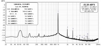
Sorry missed your post before. When I did that test I did not follow it up with any listening impressions so can't comment on the sound. However I decided since my setup has changed since then I would revisit how the amp performs at 6K. The big changes since that test are a higher B+ at 425V and R7 at 0.6K. Interesting results. 1W at 0.079% THD and 5% THD at 13W. The amp becomes 3H dominant at around 3W of output but not massively so and 2H and 3H remain relatively close all the way to clipping. A bit of the higher orders coming up to but that 1W THD number surprised me. I may play with this a bit more and give it a listen.ref. post #240, TDH apart, how was the sound at 3k and 6k Ra? Which you liked most and why?
Thanks
Attachments
Gave it one more quick test tonight. Bumped B+ up to 450V. 1W distortion the same at 0.079% and THD 5% at 14.5W so a little more output. THD at 10W is 0.8% Hopefully I'll have time tomorrow for some listening.
Gave it a good listen Setup with B+ 450V and 6K OPT wiring with the 26HU5/12GN7A combo. I used a couple of different setting on the pots with 1W THD anywhere from 0.06 - 0.45%. Overall differences are subtle compared to running it with B+ 425V and 3K OPT wiring. However my overall impression is it sounds a bit thinner, just seems to be lacking that extra bit of fullness and drive. Caveat this is running into my garage speakers which are some old Sony 3 ways that came with an integrated system so my guess is if you had some efficient full rangers it would drive the with plenty of gusto.
For myself my current favorite setup with the UNSET is with the 3K OPT and dialed in (105V driver plate and 94mA output tube) for about 0.55% THD at 1W giving a nice 2H dominant distortion spectra. Like this 2H remains dominant all the way to clipping with 5% THD just shy of 18W.
For myself my current favorite setup with the UNSET is with the 3K OPT and dialed in (105V driver plate and 94mA output tube) for about 0.55% THD at 1W giving a nice 2H dominant distortion spectra. Like this 2H remains dominant all the way to clipping with 5% THD just shy of 18W.
Thanks for your listening experiments and assessments. Just to be clear, what is the B+ in your favorite setup above?For myself my current favorite setup with the UNSET is with the 3K OPT and dialed in (105V driver plate and 94mA output tube) for about 0.55% THD at 1W giving a nice 2H dominant distortion spectra. Like this 2H remains dominant all the way to clipping with 5% THD just shy of 18W.
Same impression with bass notes. Nice and defined with both setups but they just sound a bit fuller and punchy with the 3K OPT. Again it is subtle, much like it was adding in the external motor run caps.@spiggs
thank you for the test at 6k OPT and 450V B+.
Midrange is better at 3k, but what is the difference in performance on bass notes?
B+ is 425VThanks for your listening experiments and assessments. Just to be clear, what is the B+ in your favorite setup above?
I have run into a problem. The base of C203 is now measuring 345V and does not respond to any adjustment of the pot. C103 still measures normal at around 110V where I set it. I tried swapping driver tubes but no difference. Leading up to this I have been swapping in different heater supplies and pulled the tubes a few times in an effort to track down some 60hZ distortion so it is most likely something I did. Any ideas on what the most likely culprit is?
I assume that you mean that the plate voltage on V201 is 345 volts, and pot R204 has no effect? If so that tube is not conducting at all. If V101 is still functioning properly the parts associated with the zener diode are OK. First make sure that the heater of V201 is hot, as broken pins or solder joints on a tube socket are not uncommon. If hot, then R209 or Q201 may be open. Resistors often look burnt when open, but sometimes show no outward signs, especially if subjected to a brief but intense overload like an accidental screwdriver or voltmeter probe slip. Silicon creatures usually fail to a short which would make the plate voltage very low, but anything is possible.I have run into a problem. The base of C203 is now measuring 345V and does not respond to any adjustment of the pot. C103 still measures normal at around 110V where I set it. I tried swapping driver tubes but no difference. Leading up to this I have been swapping in different heater supplies and pulled the tubes a few times in an effort to track down some 60hZ distortion so it is most likely something I did. Any ideas on what the most likely culprit is?
If this doesn't help, please post DC voltage readings on the pins of V201 and note if any of the voltages change when pot R204 is turned.
I have some of my workbench operational, but had to remove the UNSET board to do some testing on a TSE-II board. I have decided to start selling off some of my excess "stuff" so I am currently testing and grading out about 70 5842 tubes in a TSE-II board for eventual sale.
The biggest hamfest and electronics swap meet in the world is 6 weeks away. I will be there with a van full of stuff that I will not use in what's left of my life.
Last edited:
Thanks George. It ended up being Q201. I put in an order for some spares since I had to rob one from my other UNSET board to get it going again. Wish i was local to that hamfest, I would definitely stop by and lighten your load back some. Good luck with the sales.I assume that you mean that the plate voltage on V201 is 345 volts, and pot R204 has no effect? If so that tube is not conducting at all. If V101 is still functioning properly the parts associated with the zener diode are OK. First make sure that the heater of V201 is hot, as broken pins or solder joints on a tube socket are not uncommon. If hot, then R209 or Q201 may be open. Resistors often look burnt when open, but sometimes show no outward signs, especially if subjected to a brief but intense overload like an accidental screwdriver or voltmeter probe slip. Silicon creatures usually fail to a short which would make the plate voltage very low, but anything is possible.
If this doesn't help, please post DC voltage readings on the pins of V201 and note if any of the voltages change when pot R204 is turned.
I have some of my workbench operational, but had to remove the UNSET board to do some testing on a TSE-II board. I have decided to start selling off some of my excess "stuff" so I am currently testing and grading out about 70 5842 tubes in a TSE-II board for eventual sale.
The biggest hamfest and electronics swap meet in the world is 6 weeks away. I will be there with a van full of stuff that I will not use in what's left of my life.
spiggs,
Glad you are in business again! Do you think it was a random event/accident, or should we stock up on those transistors?
Which hamfest are you going to, George? Good luck!
Glad you are in business again! Do you think it was a random event/accident, or should we stock up on those transistors?
Which hamfest are you going to, George? Good luck!
- Home
- More Vendors...
- Tubelab
- UNSET Beta Board Build