Or to glue in some tubes. Possible but it's easier to make the holes part of the model.It is best to "drill" the holes to the model - so that you have shell material around the bolts. If you drill through prints, the holes will not be good and will weaken the print.
I see what you mean - as this is not a solid. Hmm, I cant perform that 3D CAD work myself I'm afraid...I can twiddle in Sketchup - thats all... help pretty please??
Maybe I could glue in 8mm solid insets that holds the 5,2mm holes? - OK mabat suggested this also I see now 🙂
//
Maybe I could glue in 8mm solid insets that holds the 5,2mm holes? - OK mabat suggested this also I see now 🙂
//
If it were me, but I would never do this myself, I would start OS - all the way around at the throat - and as gradually as possible morph to square at the mouth (including a flare.) This is likely the best that you can do with a round to square situation. But, as I said, I would stick with round everywhere, or elliptical, if it's not too squashed. Sharp corners cause diffractions, which I have measured.I skipped the obvious: a necessary mouth piece for transition from rect to circ, but as short as possible.
Maybe that doesn’t make it sampler though.
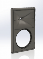
Scripted enclosures!?- A small step further in generating an enclosure:
View attachment 1035574 View attachment 1035575
View attachment 1035577 View attachment 1035579
View attachment 1035580
Yes, of course. The third option being all edges rounded - that remains to be coded.
I do it as an exercise to prove that freestanding waveguides can't be easily beaten 🙂
(It will be possible to optimize the enclosure dimensions along with the waveguide - if there's anything to be gained with that. And also to see clearly the influence of different rounding of the edges.)
I do it as an exercise to prove that freestanding waveguides can't be easily beaten 🙂
(It will be possible to optimize the enclosure dimensions along with the waveguide - if there's anything to be gained with that. And also to see clearly the influence of different rounding of the edges.)
Last edited:

Darn! My next WG will be a stand alone I think!
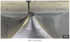
Here is the finish cut on my new boxed 400x290x100 round to rect WG. This section forms part of a full baffle mould tool. Most likekly GRP or carbon if I have any left from bike frame experiements. The corners of the WG blend out to 8mm radius with a baffle edge radius of 30mm. Render shown.
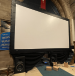
The previous DIY project using ATH4 was well received at a church cinema night. See the image below. Thanks mabat for your amazing tool. So many good words, especially the clarity of voices all round the nave.
eBay is amazing for some things. A while back I picked up large 16ft screen and a Christie DHD800 with a long throw. It was very little money and still super bright!
Here is the finish cut on my new boxed 400x290x100 round to rect WG. This section forms part of a full baffle mould tool. Most likekly GRP or carbon if I have any left from bike frame experiements. The corners of the WG blend out to 8mm radius with a baffle edge radius of 30mm. Render shown.
The previous DIY project using ATH4 was well received at a church cinema night. See the image below. Thanks mabat for your amazing tool. So many good words, especially the clarity of voices all round the nave.
eBay is amazing for some things. A while back I picked up large 16ft screen and a Christie DHD800 with a long throw. It was very little money and still super bright!
Attachments
Last edited:
Awesome!Yes, of course. The third option being all edges rounded - that remains to be coded.
I do it as an exercise to prove that freestanding waveguides can't be easily beaten 🙂
(It will be possible to optimize the enclosure dimensions along with the waveguide - if there's anything to be gained with that. And also to see clearly the influence of different rounding of the edges.)
Will it be possible to have the walls of the box not parallel?
Will it be possible to have a different radius for each edge?

That's exactly what can be done with the tool at the moment. It's never enough 🙂If it were me, but I would never do this myself, I would start OS - all the way around at the throat - and as gradually as possible morph to square at the mouth (including a flare.) This is likely the best that you can do with a round to square situation. [...]
I didn't plan that but can think about the non-parallel side walls, that should not be a big compilation.Awesome!
Will it be possible to have the walls of the box not parallel?
Will it be possible to have a different radius for each edge?
Wow, I wish I had those capabilities and tooling. Wonderful job, unrivaled.Here is the finish cut on my new boxed 400x290x100 round to rect WG. This section forms part of a full baffle mould tool. [..]
I do it as an exercise to prove that freestanding waveguides can't be easily beaten 🙂
I am very glad your ambitions show these side effect, thank you for all the wonderful work.
I think Earl once expressed a wish to see the influence of the back edge rounding. Now it's easily possible so here's a small example (box 245 x 264 x 200 mm). I only should probably chose a bigger rounding radius (and I'll do that again).
Flat back


Rounded back (R=25mm)


SPL differences on-axis and 20deg off-axis:

Flat back
Rounded back (R=25mm)
SPL differences on-axis and 20deg off-axis:
Stunning work!I think Earl once expressed a wish to see the influence of the back edge rounding. Now it's easily possible so here's a small example (box 245 x 264 x 200 mm). I only should probably chose a bigger rounding radius (and I'll do that again).
Flat back
View attachment 1035813 View attachment 1035814 View attachment 1035815
Rounded back (R=25mm)
View attachment 1035816 View attachment 1035817 View attachment 1035818
SPL differences on-axis and 20deg off-axis:
View attachment 1035819
I've been recently researching SLA/DLP/LED resin printers....the higher speed and accuracy, lesser moving parts, lower price of these machines, are alluring....
My thought has always been that if I can figure out how to print mainly, the inner horn/waveguide walls, Bulk could be added to the outside in the form of a mortar... it seems that resin printing is capable of printing pieces at a high enough accuracy that if the pieces were design to do so, they could be assemble to create a whole piece, rather easily, that could be glued in place.... In particular the phase plug that Mabat designed would likely be printed with Resin, very accurately, as resin seems to be conducive to that aspect.
AS far as horn or waveguide walls...I envision thin as practical parts that serve to create the inner surface, as well, hollow pieces that might be filled with mortar/epoxy or maybe even sand.
Horrible idea?
Equally very well controlled diffraction polars with the roundover of 50 mm. I wonder whether these improvements are a result of the increased radius only, or if the increased width (5 cm wider in total) and especially the decreased depth produce the more even polars. A wide but shallow baffle is not necessarily what I was looking for myself, but I am remembered of the GGNTKT M1/M2 speakers that feature a similar enclosure form.
Great work, really looking forward for this.
You will have the opportunity to examine all of this for yourself soon.
The previous box horizontally & vertically.
View attachment 1035842
Horizontal:
View attachment 1035844 View attachment 1035845
Vertical:
View attachment 1035846 View attachment 1035847
Can you extend the bottom of the enclosure by 1x its length, to show a waveguide position in a two way enclosure, and make a vertical up and vertical down polar plot, or is this still too early with current scripting means? Hefty difference between 50 mm roundover versus none.
E:
You will have the opportunity to examine all of this for yourself soon.
Great news, I will.
- Home
- Loudspeakers
- Multi-Way
- Acoustic Horn Design – The Easy Way (Ath4)