Why don't you first measure on the power supply board itself? With COM probe on GND, measure V+ and V- and see if you get +24V and -24V.
Like Dennis said, but disconnect the BA-3 to the PSU when measuring. If the bipolar voltages are present, I will check the wiring scheme from PSU to BA-3.
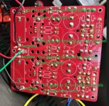
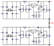
Yes you are still feeding -24 V and 0 V to one Channel and 0V and +24 V to the other Channel as before. See attached pic.I'm missing something in how I've wired between the PSU and the amp card.
Attachments
Thank you so much for taking time to reply Amanda, thanks to you and all of those who bother to read and reply my newbie questions, it all is really informative and helps to get a better understanding of the world we live in, be it music, electrons flow or whatever it is.Hi Giovanni,
...
View attachment 1034272
So, I will try my best to explain how the system operates.
Looking at the back of the preamp, a little cut off from the picture but visible, to the right of the RCA output is the main switch for line 120 VAC. This switch turns On and Off only the IRM-5-02 (On is standby, Off is totally disconnected from line voltage). When the switch is on standby, the IRM has 5V out, the Muffsy control board can be turn On by pressing the encoder switch on the faceplate of the preamp. When the Muffsy is awake, it triggers the relay, then it connects the transformers to the line voltage, then it powers the boards and so on as I described above.
Hope my description make sense.
On a lighter note, lots of knowledgeable people here to answer your questions when you build the preamp, I know because I asked a lot of questions too.
More questions sure to follow
Grazie
Chiptech,
ozorfis has identified your problem. Please do the following:
0) Remove the PS wiring.
1) Adjust P1 and P2 of both channels of BA3 pcb back down, ideally to close to zero. This is so that when you fix the PS problem and power up, you don't have crazy amount of current.
2) Measure on the PS board: With COM probe on GND, verify that you have 0 on GND, +24V on V+ and -24V on V-
3) Wire up from PS to BA3 pcb for both channels: GND (PS) to GND (BA3), V+ (PS) to V+ (BA3), V-(PS) to V-(BA3)
4) Power up again. Hopefully the reset of P1 and P2 was done correctly and you're not getting a large current draw at the mosfets. Check that you have low (ideally zero) voltage across the 22 ohm source resistors R10 and R11.
5) Check power on BA3 PCB: COM probe on GND, verify that you have +24V on V+ and -24V on V-
If all this checks out, try the biasing procedure again.
If you are still using 500R pots for the board with Fairchild mosfets be prepared to have to change the pots to 1K to set the bias level correctly.


Ben, thanks for the guidance. Steps 0 thru 2 all checked and confirmed.Chiptech,
ozorfis has identified your problem. Please do the following:
0) Remove the PS wiring.
1) Adjust P1 and P2 of both channels of BA3 pcb back down, ideally to close to zero. This is so that when you fix the PS problem and power up, you don't have crazy amount of current.
2) Measure on the PS board: With COM probe on GND, verify that you have 0 on GND, +24V on V+ and -24V on V-
3) Wire up from PS to BA3 pcb for both channels: GND (PS) to GND (BA3), V+ (PS) to V+ (BA3), V-(PS) to V-(BA3)
4) Power up again. Hopefully the reset of P1 and P2 was done correctly and you're not getting a large current draw at the mosfets. Check that you have low (ideally zero) voltage across the 22 ohm source resistors R10 and R11.
5) Check power on BA3 PCB: COM probe on GND, verify that you have +24V on V+ and -24V on V-
If all this checks out, try the biasing procedure again.
If you are still using 500R pots for the board with Fairchild mosfets be prepared to have to change the pots to 1K to set the bias level correctly.
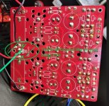
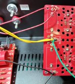
I realize I did not had a ground from the PSU to the BA3 pcb. I have grounds from both to my star ground point. See photo.
I will connect a ground wire from the PSU to the BA3 as noted by arrow, unless there is a better place?
This board uses the Fairchild mosfets and 1K pots.
Attachments
Not me. It's Dennis' great advice.
And yes, the Ground wire goes to the G on the board. See cubicincher's post:https://www.diyaudio.com/community/threads/the-ba-3-as-preamp-build-guide.258022/post-6966501
I also suggest that from the PS board you have two groups of the V+ V- G wires. Twist each group of V+ V- G together and route that to the board. Twisting the wires together reduces loop area and allows for a quieter preamp, and it also makes it easier to see what wires are going where.
Last edited:
Chip,
As ozorfis noted in the above post and in this post (https://www.diyaudio.com/community/threads/the-ba-3-as-preamp-build-guide.258022/post-6968588), all of the connection points at the middle of the PS board are Ground.
At one corner of the board is V+, which goes to the V+ at two locations on the BA-3 board and at the opposite corner of the PS board is V-, which goes to two locations on the BA-3 board.
Do not be confused or mislead by the markings on the centre of the PS board which show V+ Gnd V-. Those are all Ground.
From Glass-ware website:
Attachments
ThiLast attempt: see pic attached
Ozorfis is correct! As I said, I really think its the wiring scheme. Ben gave you the simplest explanation of the GND connections.Chip,
As ozorfis noted in the above post and in this post (https://www.diyaudio.com/community/threads/the-ba-3-as-preamp-build-guide.258022/post-6968588), all of the connection points at the middle of the PS board are Ground.
At one corner of the board is V+, which goes to the V+ at two locations on the BA-3 board and at the opposite corner of the PS board is V-, which goes to two locations on the BA-3 board.
Do not be confused or mislead by the markings on the centre of the PS board which show V+ Gnd V-. Those are all Ground.
V- (bottom edges)is the neg. V supply, V+ (on the top edges) is the +V supply, G is the GND (connect to Ground of the supply), D is the signal ground (Inputs R and L negative).
Last edited:
Chiptech,
Ben and Ozorfis are correct.
V+ and V- are at the corner of your PS pcb. And as it was pointed out a while back, all that stuff in the centre
are all tied together and are all GND.
Please rewire with this in mind.
Ben and Ozorfis are correct.
V+ and V- are at the corner of your PS pcb. And as it was pointed out a while back, all that stuff in the centre
are all tied together and are all GND.
Please rewire with this in mind.
Oops, thanks Dennis.
And everyone, for cracking the code on this.
Lots to do.
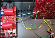
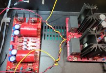
Here's a start.
And everyone, for cracking the code on this.
Lots to do.
Here's a start.
Attachments
Last edited:
Awesome - that looks good. 👍Here's a start.
As stated before by our friends: Remember to turn the pots down before you power up.
Attachments
I don't think you can say turn down the pots enough. And I have. Tomorrow's adventure.Awesome - that looks good. 👍
As stated before by our friends: Remember to turn the pots down before you power up.
Chiptech,
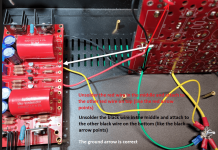
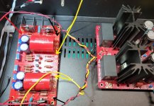
One last thing: Can you please confirm where that green wire at 'GND' goes? Does it go directly to a chassis connection, and if so, is that chassis connection then directly connected to IEC EARTH?
If this is the configuration and you find the preamp noisy then you'll probably need to provide some isolation to your audio circuit GND by adding, for example, a CL60 thermistor between the green wire and the chassis connection.
Can anyone recommend a substitute for the Q4 substitute? FQP3N30 is out of stock at Digi-Key and Mouser. I can get it from Newark (ships from UK) but I'm curious if there's an alternative available from Digi-Key or Mouser.
I ordered from these guys:
https://www.arrow.com/en/products/fqp3n30/on-semiconductor?q=FQP3N30
I also stocked up on some other mosfets from there as the pricing is decent. They are very reputable.
https://www.arrow.com/en/products/fqp3n30/on-semiconductor?q=FQP3N30
I also stocked up on some other mosfets from there as the pricing is decent. They are very reputable.
Getting ready to turn on. 6L6 in post #2 references:
Place one voltmeter (Set to DC volts) from R12 to ground - to observe DC offset
Where should I place the probe for ground?
I think I read somewhere [but can't find now] to place the probe at the front lead of C3?
Place one voltmeter (Set to DC volts) from R12 to ground - to observe DC offset
Where should I place the probe for ground?
I think I read somewhere [but can't find now] to place the probe at the front lead of C3?
- Home
- Amplifiers
- Pass Labs
- The BA-3 as preamp build guide