Like I saidThe fuses blew up and I see that the leds on the board lit up fine during this period. But looks like the amp board has some issues 🙁
Which version of the boards did you get it printed now?My new board cleared customs. I will get it in 2-3 days and will try to start it up.
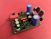
I took a risk now and powered up the amp without the fuses in dc rails. I see that in few seconds the trace near the negative supply next to the cap burnt up. Silk screen is damaged but the trace is intact. I switched off the amp immediately. It is still with the FQP3P20/FQP3N30 mosfets. All mosfets seem to be fine post this but not sure why this trace alone got burnt up. Even the mosfet here with the bulb tester was getting hot even though the other power mosfet was not even warm.Like I said
Mini version. I put the coil away.Which version of the boards did you get it printed now?
Made the input filter

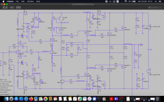
Can you show me the diagramI have now also found a fairly stable variant.
I took a risk now and powered up the amp without the fuses in dc rails. I see that in few seconds the trace near the negative supply next to the cap burnt up. Silk screen is damaged but the trace is intact. I switched off the amp immediately. It is still with the FQP3P20/FQP3N30 mosfets. All mosfets seem to be fine post this but not sure why this trace alone got burnt up. Even the mosfet here with the bulb tester was getting hot even though the other power mosfet was not even warm.
It wasn't a very good idea. If the fuses blow it's for a good reason.
Q16 must be shorted (dead). Check R between GNDPWR and NEG rail.
Stef.
Last edited:
Q16 seems to be good in the DMM shorting test. What do you mean by "Check R between GNDPWR and NEG rail" as I am using a PSU based on LT4320 where by I have shorted the resistors with a lead. I do not see any resistor on the amp board between the G and Negative rail.Q16 must be shorted (dead). Check R between GNDPWR and NEG rail.
Stef.
You have a short contact somewhere. Disconnect all cables and check resistance between GNDPWR and positive rail and negative rail. Check resistance between Q5, Q6, Q15 and Q16 metal part and GNDPWR. Should not be zero Ohms. Same with dissipator.
Stef.
Stef.
Sure thanks Stef will check. When you say check resistance between Q5/6/15/16 metal part you mean each leg of the transistors against the ground power on the supply side?You have a short contact somewhere. Disconnect all cables and check resistance between GNDPWR and positive rail and negative rail. Check resistance between Q5, Q6, Q15 and Q16 metal part and GNDPWR. Should not be zero Ohms. Same with dissipator.
Stef.
That's not it. Here's a video. Without op-amps all the power is normal, after installing op-amps, we get.You have a short contact somewhere.
If there was a short circuit, the amplifier would not work without the op-amps. AND NOTHING WOULD BURN OUT WITHOUT THE OP-AMPS.
Just a crude circuit, the amplifier is not stable.
The one on the video is definitely not an OPA1641. This amplifier definitely only works with very very few OPs!
This is lm49710. But it doesn't change the essence. It's exactly the same with the OPA1641. I can make a video with 1641 as well. The video proves that there is no short circuit on the board and the power supply is fine.
One more thing, you have C7 as an MKS? That's a rather compact film capacitor in your case, isn't it? You don't need the yellow one at the input because of the DC correction of the amplifier, does it have approx. 1uF and can you install it as C7 as a test?
The point is that your symptoms mean that the OP cannot find the operating point. I have such effects when R13 varies slightly in value. In your case, it seems that the OP has a problem in the feedback.
I looked at your PCB, it looks like Q9 + Q11 are installed in reverse, is that possible!
The point is that your symptoms mean that the OP cannot find the operating point. I have such effects when R13 varies slightly in value. In your case, it seems that the OP has a problem in the feedback.
I looked at your PCB, it looks like Q9 + Q11 are installed in reverse, is that possible!
Last edited:
Sure thanks Stef will check. When you say check resistance between Q5/6/15/16 metal part you mean each leg of the transistors against the ground power on the supply side?
The metal part with the green cross. Check isolation of power transistors from heatsink too.
Stef.
Attachments
Thanks Stef, I always check each of the mosfets metal base for shorting to the heat sinks or not before powering up. I also checked each leg of the mosfet against the heat sink for shorting. None was their as I use a silicon thermal pad and grease. But I have not checked the ground power to the negative/positive rails and against the mosfet metal part. Will check that and for the last try will replace the FQP3N30/FQP3P20 with 610/9610 and run the amp. Also what do you suggest the input signal to be shorted during the testing of the amp which I usually do in all my class A amp builds.The metal part with the green cross. Check isolation of power transistors from heatsink too.
Stef.
C7 = 1uF. I tried it without 4.7uF at the input. I will try to check everything again.One more thing, you have C7 as an MKS?
They are standing correctly, according to the diagram. Replacing C7 with polypropylene did nothing. I will put this board aside for now, I don't know what else to check.Q9 + Q11 are installed in reverse, is that possible!
You may have a problem with opamp itself, or a faulty component. Check capacitors first.That's not it. Here's a video. Without op-amps all the power is normal, after installing op-amps, we get.
If there was a short circuit, the amplifier would not work without the op-amps. AND NOTHING WOULD BURN OUT WITHOUT THE OP-AMPS.
Just a crude circuit, the amplifier is not stable.
Have attached a simulation copy. Look at voltage test point and see if you are near.
Regards,
Tibi
Attachments
- Home
- Amplifiers
- Solid State
- Q17 - an audiophile approach to perfect sound