It turns out that I did do SPICE simulations with the input filter bypassed back when I was posting to the Cordell thread. I just ran it again and the simulated response looks exactly like the scope photo I posted earlier today. Also, the size of the feedback capacitor doesn't make any noticeable difference to the overshoot.
I'm amazed how good the simulations are at predicting real-world behavior. The only thing they seem to screw up badly is saturation and clipping, but that makes sense because SPICE is a small-signal simulator. I assume SPICE is accurately reflecting the different component choices in our two versions of the amp.
Can you post your SPICE file? I'd like to see this ringing for myself. I was playing around and couldn't get it to misbehave. I don't guarantee when I'll have time to get to it, but I'm really curious what the difference is.
It was originally a digital simulator. It should give "a right answer" as nodes are slammed to the rails. True, some fine detail will be omitted because it is not likely to affect the final digital level. But this may be more a model limitation than the algorithm.SPICE is a small-signal simulator.
I think you're right. I was confusing the .ac analysis, which I believe is definitely small-signal, with the .tran analysis which is not. I admit I don't know much about how SPICE works internally.
It makes sense, if the analysis were small-signal, that you couldn't predict distortion at all with SPICE. Which is clearly not true.
So strike my previous statement. Instead, I'll say I've had some epic fails with SPICE. It totally missed the amazing clipping shenanigans of my original version of A1. Last fall, I designed (for a friend) a replacement for an unobtanium Yamaha driver module, and ran into some really weird behavior on the bench that didn't show in the simulator.
As you say, it's probably the models that aren't so realistic. Thanks for pointing that out.
Yes.I've had some epic fails with SPICE.
Most of the time, I find the problem on 'my side of the screen'. SPICE actually gives the right answer for the question I entered, not the question I had in my mind. Forgetting the u on a cap, simple wrong circuit, mistyped variable name. And because I don't have great models at hand, the answer may be a "wax impression" rather than a good representation.
Sure, no problem. I'll send them now by pm, as they aren't ready or in a fit state for publication!Can you post your SPICE file? I'd like to see this ringing for myself. I was playing around and couldn't get it to misbehave. I don't guarantee when I'll have time to get to it, but I'm really curious what the difference is.
Thanks. I will look at the simulation this weekend.
I built a power supply tonight.

The kitten found use for the empty Mouser box.

Edit: I just realized -- "Kitten... Mouser." Haha, joke.
I built a power supply tonight.
The kitten found use for the empty Mouser box.
Edit: I just realized -- "Kitten... Mouser." Haha, joke.

There's a blizzard outside. I went to You Do It Electronics last night to buy hookup wire and they had closed early. I'm not optimistic they will open today, but I can make do with the wire I have on hand. I made some progress with the mechanical part of building the A3 breadboard last night. With luck, I will have it running by tonight.
😆 Much cuter than the usual contents.Edit: I just realized -- "Kitten... Mouser." Haha, joke.
The power supply looks very nice.
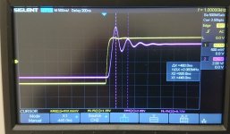
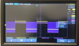
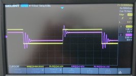
Hi All. A quick update (part 1) – testing my implementation of Henry’s “A2” with capacitive loading. 1 kHz, 2 Vpp square wave, no input low-pass filter. 33R load in parallel with 1, 10 and 100nF. At 1 nF things look very similar to the 33R alone (see earlier post) – some ringing at ~2.1 MHz. The amplitude is now a little higher. At 10 nF we have higher amplitude ringing, now at ~1.4 MHz. This frequency looks like ringing from the ~1u output inductor and the 10nF load capacitor, rather than the amp itself. At 100 nF – ouch, now we have oscillation! This was not always self-sustaining after muting the signal generator, but it did self-sustain once or twice out of perhaps 4 very short tests. With a ~200 kHz RC input filter in place, the same 33R+100nF load shows some damped ringing at 460 kHz, again consistent with ringing of the output inductor and 100nF load.
So looks like a little tweaking is needed - some results coming in part 2. One thing that I did notice in simulations of this circuit is that the LSK389B that I’m using in the IPS does behave differently to the 2N5564 that Henry originally used. The LSK389B is less well behaved. Could this be one reason why we’re seeing some different behaviour?
So looks like a little tweaking is needed - some results coming in part 2. One thing that I did notice in simulations of this circuit is that the LSK389B that I’m using in the IPS does behave differently to the 2N5564 that Henry originally used. The LSK389B is less well behaved. Could this be one reason why we’re seeing some different behaviour?
Attachments

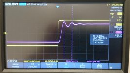
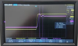
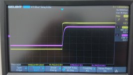
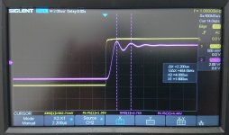
Update (part 2) – I thought it would make more sense to read if split things into a “before” and “after” post. I replaced the 10 pF capacitor across the feedback resistor with 33 pF. Simulations suggested that this would improve the phase margin. After repeating the square wave tests above things do indeed look better. With 33R alone there is still some ringing, now at ~2.6 MHz, but the amplitude is reduced and it decays more quickly. With 33R + 100 nF there’s no longer any oscillation, just some ringing at ~450 kHz, again consistent with the output inductor and 100 nF capacitor. With a ~200 kHz RC input filter in place the 33R load alone looks good, no sign of any of the unpleasantness seen before on the leading edge of the square wave. With 33R + 100 nF and the input filter there’s still some low amplitude ringing at 450 kHz.
So a good improvement. With the input filter in place the amp looks stable and I guess should be usable. Part of me wants to keep tweaking to reduce the small amount of ringing into the purely resistive load with the input filter disengaged. Henry’s amp only showed a small overshoot and no ringing, so it is possible to do better. However, when I tinker too much I tend to break things, so I think it’s time to take a pause and consider the next step!
So a good improvement. With the input filter in place the amp looks stable and I guess should be usable. Part of me wants to keep tweaking to reduce the small amount of ringing into the purely resistive load with the input filter disengaged. Henry’s amp only showed a small overshoot and no ringing, so it is possible to do better. However, when I tinker too much I tend to break things, so I think it’s time to take a pause and consider the next step!
Attachments
By the way, please let me know if my posts are distracting from your updates on progress on the "A3" and I will stop. I don't want to derail your thread now that the focus is not on the "A2".
By the way, please let me know if my posts are distracting from your updates on progress on the "A3" and I will stop. I don't want to derail your thread now that the focus is not on the "A2".
Oh, not at all! This is everybody's thread, and your posts are totally on topic, and extremely interesting to me and I'm sure to others, too.
Darth Kittius woke me up at around 6:00 AM. I'm struggling on five hours of sleep, and it's a major nuisance to get out to the garage right now. But I'm almost ready to test the amp.
I will try to get to your simulation tonight.


I'm listening to this now. I still need to make a 12V supply for the muting relay, so running that with my bench supply.
I want to let it warm up and break in a bit before I try to describe the sound. TBH, I'm doubting my credentials as a "subjective reviewer" at this point, so I don't know how useful my comments will be anyway.
I don't have the impression I had before that the amp is so colored. This Super Regulator is tight as a... well.. it's stiff. So should be very good sound, but probably not the same sound as with the official power supply.
My general impression is much the same as before: very pleasant and relaxed to listen to with lots of good stuff going on, but not the laser focus of my other amps, including the Topping.
More later.
Looking great! I really like your testing setup. Looks like a very useful way to get power and signals in/out before your creations get finally boxed up. I think I will have to build something similar at some point.
Thanks! I really appreciate the chance to bounce ideas around about these amps.Oh, not at all! This is everybody's thread, and your posts are totally on topic.
- Home
- Amplifiers
- Headphone Systems
- New Headphone Amplifier Design