Oh calamity! Sorry to hear this. Good luck with the fix. Hope you got your IXTP3N100D2 ordered - I see Mouser has only 3 in stock now.
When you have a chance, please do tell more about achieving “~.1% THD at 1W”.
When you have a chance, please do tell more about achieving “~.1% THD at 1W”.
The 0.1% THD is the variation I was seeing at 1W between different output tubes. Say a pair of GE tubes gave ~0.6% at 1 W then a pair of RCA tubes may have had ~0.7% and so on. I was curious how consistent the results would be among the various flavors of 6DQ5 tubes I have.
Last edited:
Pulled the Q1 mosfet and resistor between the drain and PCB. The mosfet now tests as a resistor on my cheap component tester and the 2K resistor now tests as a 3.8K resistor. Digging around reminded me that I had ordered a few extra IXTP3N100D2s and I had some cheap 2K 5W cement resistors so I soldered those in and am back in business. Also managed to pull the anode cap off one of the output tubes on disassembly but a little JB weld and solder has got it working again. My UNSET is back to playing music.
So where am I at now? Here is a summary of the changes and my current setup.
R113/R213 33K (suggested by George)
R108/R208 92K (trial and error)
Choke replaced with a Neurochrome Maida style regulator
C2 10uF motor run cap (value suggested by Tom at Neurochrome for use with regulator)
C1 Added 2 100uF motor run caps in parallel with the 47uF on PCB (total 247uF) by repurposing the rectifier tube heater connector
Wired 6DQ5 output tube heaters in series to run at 12.6V
12GH7A driver tubes
12V SMPS adjusted for 12.6V with filter for heaters
B+ set to 325V measured at C2
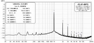
I can adjust THD at 1W from anywhere between 0.3% - 1.2% or more using the pots but to me it sounds best with it adjusted in the 0.6 - 0.7% range and this corresponds to a H2 dominant FFT, 5% THD is around 13W. I don't think the regulated B+ and filtered SMPS heater PSU added anything to the performance, it just gave me a way to try different voltages and have a little fun with different setups. Also George mentioned that reducing the value of R108/R208 would reduce gain. With it at 92K I can still drive the amp to clipping using just my phone or DAC as input.
George hope all is well with you and you don't mind me clogging up this thread with all my uneducated tweaking (comic relief perhaps?). This is good fun for me.
So where am I at now? Here is a summary of the changes and my current setup.
R113/R213 33K (suggested by George)
R108/R208 92K (trial and error)
Choke replaced with a Neurochrome Maida style regulator
C2 10uF motor run cap (value suggested by Tom at Neurochrome for use with regulator)
C1 Added 2 100uF motor run caps in parallel with the 47uF on PCB (total 247uF) by repurposing the rectifier tube heater connector
Wired 6DQ5 output tube heaters in series to run at 12.6V
12GH7A driver tubes
12V SMPS adjusted for 12.6V with filter for heaters
B+ set to 325V measured at C2
I can adjust THD at 1W from anywhere between 0.3% - 1.2% or more using the pots but to me it sounds best with it adjusted in the 0.6 - 0.7% range and this corresponds to a H2 dominant FFT, 5% THD is around 13W. I don't think the regulated B+ and filtered SMPS heater PSU added anything to the performance, it just gave me a way to try different voltages and have a little fun with different setups. Also George mentioned that reducing the value of R108/R208 would reduce gain. With it at 92K I can still drive the amp to clipping using just my phone or DAC as input.
George hope all is well with you and you don't mind me clogging up this thread with all my uneducated tweaking (comic relief perhaps?). This is good fun for me.
When I did the experiments with the R108/R208 resistor values it was using the 12GH7A driver tubes. I decided to see how the new resistor values worked using the 6J51P as the driver tubes. Awful is the answer. I could not get the amp to remain stable while trying to dial in the plate voltage for any reasonable amount of distortion. Seems like I took some flexibility out of the design with that change.
Thanks, spiggs! Useful information to keep in mind. I had planned to use 6EJ7 initially, and later try 12GH7A. But I also have Russian 6J51P tubes and will be very cautious with those.
George. Do you have any thoughts or advice on the change in R108/R208 I did? Seems to give better results when using the 12GH7A tubes but has made the 6EJ7 unusable. I am only using the FFT graph as my gauge of performance and don't mind optimizing for one type of driver tube since I have a few of these. However are there other parameters that I should be looking at?
I also have a more general question. If I wire the 2 6.3VAC windings on the transformer in series to give 12.6VAC is there any issues with connecting the center tap to the same ground as the HV center tap?
I also have a more general question. If I wire the 2 6.3VAC windings on the transformer in series to give 12.6VAC is there any issues with connecting the center tap to the same ground as the HV center tap?
spiggs, I guess we are alone in this echo chamber now, so I don’t think you are clogging the thread at all 😁.
Your question relating to the “wire the 2 6.3VAC windings on the transformer in series to give 12.6VAC” - is this to light up the output tubes? Looks like the heaters on the output tubes are referenced to the cathode voltage via R118 and. R218, so I would think the center tap should not be grounded. The driver tube heater is also lifted.
Small clarification (for the record) - you wrote 12GH7a for your driver tube in post #203 & 206. I assume you meant 12GN7a. (I followed example in #205).
Last edited:
Yes seems so, thanks for the reply 👍. Correct 12GN7A is what I am using, boxes are labeled 12GN7A/12GH7. I was thinking of trying the AC windings again for the heaters to see how it impacts the noise floor.spiggs, I guess we are alone in this echo chamber now, so I don’t think you are clogging the thread at all 😁.
Your question relating to the “wire the 2 6.3VAC windings on the transformer in series to give 12.6VAC” - is this to light up the output tubes? Looks like the heaters on the output tubes are referenced to the cathode voltage via R118 and. R218, so I would think the center tap should not be grounded. The driver tube heater is also lifted.
Small clarification (for the record) - you wrote 12GH7a for your driver tube in post #203 & 206. I assume you meant 12GN7a. (I followed example in #205).
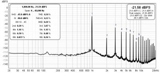
Attached are the FFT graphs of the current setup with the amp adjusted for 0.65% THD at 1W. This is where it sounds best to me even though I can adjust the THD lower. This also shows where the noise floor is with the SMPS driving the heaters and a regulated B+ but of course no case. The second graph is THD at about 12W output.
Attachments
I agree that 1% at 1 watt is too high, and I have measured far better than that in my amp.I hope we could figure this out as well as the ~1% distortion at 1 watt. The UNSET could not be called a Hifi amp with those distortion figures at 1 watt.
Remember that we are attempting to replicate a SET amp with a TV sweep tube. The typical SET rarely does much better than this. A typical 300B amp may get 9 or 10 watts from 34 watts of dissipation. A TV sweep tube run in triode mode is restricted to a low plate voltage due to its low screen voltage spec. A TV sweep tube can be run in SE pentode mode and cleaned up with feedback, but the curves don't start looking very linear until the dissipation is near or into the red plate region for class A operation. The UNSET attempts to dance around these limitations. Again, more than the 40% seen here should be attainable.0.5% at 1 watt and 13.7 watts at 5% look better. But your 6DQ5 is dissipating 34 watts! Not the efficiency expected from UNSET topology.
Your experience is what drives the whole SET trend. Many SE users prefer a bit of 2H over a perfectly clean signal. The amount of 2H preferred depends on the user and the makeup of the harmonic profile. A bit of 3H, which is musically related to the fundamental can also be tolerated and provides "brightness" on loud notes. The 5th harmonic is dissonant as are all higher odd order harmonics. Even at low levels they cause listener fatigue, as does any IMD.I can adjust THD at 1W from anywhere between 0.3% - 1.2% or more using the pots but to me it sounds best with it adjusted in the 0.6 - 0.7% range and this corresponds to a H2 dominant FFT, 5% THD is around 13W.
In all of my previous board designs I spent an undue amount of time building, tweaking and testing my design before even mentioning that it existed. At that time, I was a product designer at Motorola doing public safety (police, fire, military...) radios where someone's life may depend on that radio working correctly even in extreme conditions. I learned how to make expensive reliable products, but the design cycle was often quite long, sometimes 3 or more years. Every component went through rigorous testing before being considered for use. I used that knowledge and experience to create some boards that range from "build and play" (the SSE and SPP) to build it, set it up, maybe tweak it a bit and play (the TSE and TSE-II) to this is a building block in a bigger design (the Universal Driver Board). The UNSET beta version never got the benefit of some serious testing and tweaking time.
The CED circuit came about several years ago and was tweaked to death over several periods of time. The first amp design was a push pull breadboard that got 50 to 80 WPC from some tiny tubes built back in 2018. The SET design was first done in the LTspice simulator, where it showed promise, so I laid out a board, made a DIY proto board and built it. After a few weeks of testing a complete amp was built which was my primary listening amp for nearly a year. There were a few tweaks during that year, but the board remained much like it was the day I made it. I did not like the original jumper plug system for using different octal tubes, so I did a second board with the current pads. Most of the parts in the board are still the same as in the simulation, which was done with a 6EJ7 and a 6DQ5. During this time, it became necessary to stop all work on UNSET and redesign the TSE. Unset work resumed in mid 2020 after nearly a year. Several personal and Tubelab related diversions put large gaps of time in that work. The UNSET board got far less than the usual attention and it began to look like it would never make it to a product. After several emails and forum posts I agreed to take the second prototype version board, clean it up, fix the known issues and have 25 boards made last April. They were offered for sale in July, and 11 orders have occurred since then.
I have been silent for some time. This is due to several issues beyond my control. After taking my workspace apart to fix an unsafe condition I went through a rough bout of what is believed to be gout. This ended the workbench rebuild project, leaving an unworkable mess behind. For the past three weeks I could barely get up and down the basement stairs where the workshop and computers reside. I do have a laptop upstairs and have read every post here.spiggs, I guess we are alone in this echo chamber now, so I don’t think you are clogging the thread at all 😁.
At this moment Tubelab board orders, which pay for my experiments, have dropped to near zero at a time when the DIY audio hobby usually picks up. This is due to parts shortages and outright unavailability. The IXYS 10M45s chip that is a key part in my two best selling boards has disappeared. Mouser is quoting January of 2023 for availability. My bench time will be devoted to testing alternative parts as soon as I can.
So far there appear to be two people plus myself actively playing with these boards. Anything you guys find is worthwhile info and will be investigated as time permits. I will post some more info on how to tweak the board and what to look for as time permits.
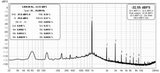
My first amp build was the ACA and I found that to be a good sounding amp. Research for the next project exposed me to the war that seems to rage between those who find any measurable distortion intolerable vs those who seek reasonable or even desired distortion profiles. To see for myself what I would prefer I picked 2 amps as representative of both views, a Modulus 86 and Tubelab SSE. I built both and swapped them in my living room system giving each a good long (months) listening. What I found is I preferred the SSE. I thought about trying a 300b build next but reading about the UNSET development it seemed to potentially promise more of what I was enjoying plus it is a whole lot cheaper to stock up on spare tubes and would provide more of a learning experience. So far testing has shown me that I do fall into the camp of SE users that prefer a dominant 2H profile. Just for fun attached is my UNSET build adjusted for lowest THD I can achieve at 1W disregarding the distortion profile.Your experience is what drives the whole SET trend. Many SE users prefer a bit of 2H over a perfectly clean signal. The amount of 2H preferred depends on the user and the makeup of the harmonic profile. A bit of 3H, which is musically related to the fundamental can also be tolerated and provides "brightness" on loud notes. The 5th harmonic is dissonant as are all higher odd order harmonics. Even at low levels they cause listener fatigue, as does any IMD.
Understand, I have been seeing your posts around the forum where you mention your struggles with getting some workshop time. It is awful to just sit on your hands because you can't physically get to the workbench, I know.I have been silent for some time. This is due to several issues beyond my control. After taking my workspace apart to fix an unsafe condition I went through a rough bout of what is believed to be gout. This ended the workbench rebuild project, leaving an unworkable mess behind. For the past three weeks I could barely get up and down the basement stairs where the workshop and computers reside. I do have a laptop upstairs and have read every post here.
Glad you find the info worthwhile, any pointers on tweaking the board would be appreciated. Also feel free to tell me I am totally going off the rails with any changes as I have been know to do.So far there appear to be two people plus myself actively playing with these boards. Anything you guys find is worthwhile info and will be investigated as time permits. I will post some more info on how to tweak the board and what to look for as time permits.
Attachments
One other interesting thing I noticed when testing the amp. The UNSET spends most of its output at least slightly 2H dominant but there are two crossover points. 3H becomes dominant at 4-5W of output but drops down under 2H again then rises to becomes dominant again around 10W. Total distortion follows a similar pattern with a small peak around the 4-5W mark.
One more test for the evening. Ran a 30hZ tone to see what it has for low end. 1% THD at 1W and 5% THD comes at just a little over 9W.
Hi guys,
Just to let you know I'm still here.
Life has a nasty habit of getting in the way of bench time.
Slowly, there is some progress on the housing for my low powered version.
With an actual housing, and its own power supply instead of the bench supply, I could even bring it down to my office, err living room. That would be nice.
Sure, getting 14W out of a 12W rated EL36 is fun, and I have enough replacements for when they wear out, listening to a permanent red plate setup makes me jumpy.
Besides, I don't need lots of power and the big output transformers do not match at 6k anyways.
I have another board, which I intend to use for a high voltage, high power version. Maybe with a 35W octal or off board 45W magnoval (PL519).
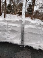
Sunday was spent preparing for the snow bomb that was coming, yesterday was spent digging out the driveway, and some of today will be spent thawing out, and cleaning up the popsicle in the driveway that used to be a Honda Pilot. We need it to drive 25 miles to the surgeon's office for back to back (tomorrow and Thursday) new holes in my body to remove more squamous cell carcinoma. Fun stuff. The picture shows the worst spot in the driveway. Overall it was 10 to 12 inches deep, not fun on a bad knee.Life has a nasty habit of getting in the way of bench time.
I will attempt to explain a bit about the UNSET tech, and how it differs from a typical two stage SET like the TSE-II. Note to avoid nit picking I state that this is a simplified explanation and does not account for all factors that create distortion.
An ideal triode should have a constant Mu (voltage gain). Many triodes have a Mu VS grid voltage or Mu VS plate current graph in their data sheet. You can see that Mu is not constant. This means that the gain of a triode changes with the applied signal, and the gain change will increase as the signal level increases. Most typical triodes will have lower gain at its current extremes, and the most gain somewhere in the middle. A "transfer curve" (Vin VS Vout) shows the gain, and an ideal element would have a straight line. If you were to plot the transfer curve of a typical triode it would have a curve with a downturn at each end. This creates distortion which is primarily second harmonic.
A typical common cathode triode gain stage (including the output stage) inverts the signal. Since the first triode "bends downward" as it inverts, the second triode works on the inverted signal partially undoing that bend. This makes it look like one triode's curve frowns while the next stage's curve smiles. This allows some cancellation of the distortion due to opposing curves. There has been lots of talk about this cancellation, but in reality, there can only be perfect cancellation if both tubes are identical and working on signal levels that are exactly the same. Some of the distortion created in the first tube is subtracted from the distortion created in the second tube. Since the first stage has gain the second stage sees a much higher signal, thus bending it (distorting) a lot more and any cancellation is minimal. Nevertheless, I have seen and measured some distortion reduction at 1KHz and medium signal levels in a two stage amp. This is why tube rolling does make a noticeable difference sometimes.
The UNSET CED stage does NOT invert the signal. Even if the two stages had similar curves, there would be no cancellation, the individual distortions will ADD to each other. This puts the UNSET at a disadvantage specs wise. Early UNSET experiments did use a typical triode wired input stage, which showed slightly better overall THD numbers, but I preferred the UNSET sound. There will always be more distortion created in the output stage than the driver stage since it works on a much higher signal level. What has NOT been done yet is to do an investigation into the distortions created in each stage individually, then see what the optimum combination is. I started down this road over a year ago I hit some potholes and roadblocks. The first big pothole is the input tube itself.
I have a lot of the typical TV IF amplifier pentodes that will work in this amp. I have several hundred 6KT6 tubes, so I set out to test a bunch, create a "typical" set of curves and have another forum member create a spice model for them. That effort consumed over a month and turned out to be a total waste of time. There IS NO typical 6KT6 tube. I have found 7 or 8 tubes labeled 6KT6 with different guts in them. I plotted curves for 2 or 3 samples of each of the 5 most common varieties. In some cases, there are almost no similarities between two different 6KT6's. No model can be created from this mess. I tried some of the other TV IF amp tubes like the 6JC6, 6JD6, and 6EJ7 to find similar issues, though not as bad as the 6KT6. I originally settled on the use of tubes with the 9 pin "9AQ" pinout since they are available world wide, and this pinout is used for three distinct applications, so there are lots to choose from. I tend to use computer simulation to get to a workable starting point, then bounce between a real world test amp and the simulation to arrive at the final design. Here the simulator may be less useful. I intend to test just the first stage on the bench as soon as I can to find all there is to know about how it really behaves.
Here is some more info.
There are three primary contributors to the gain and distortion behaviors of a given pentode tube. The load impedance, the plate current and the screen voltage. All interact heavily. The UNSET design adds yet another variable to the equation when trying to force triode like performance from the pentode, the feedback ratio. These parameters are highly dependent on each other, and all are dependent on the tube being used, primarily its Gm and its inherent distortion.
Some of the intended tubes were generally used as TV IF amplifier tubes (6KT6, 6JC6, 6JD6, 6EJ7,6EH7...) which come in two flavors, sharp cutoff and remote cutoff. Both types, or most often, one of each were used in a gain controlled amplifier chain in a TV whose gain is adjusted to complement the strength of the received signal. In this case even the "sharp cutoff" tubes have a somewhat remote cutoff characteristic that restricts their linear region to part of the curves. These tubes inherently make more THD than other pentodes, but most of the THD is second harmonic.
Some of the intended tubes were generally used as TV Video amplifier tubes (12BY7, 12GN7, 12HG7, 12HL7...). These are highly linear amplifier tubes with a sharp cutoff characteristic. They tend to have a high Gm but require a more current than an IF amp tube to be linear.
Some of the intended tubes were generally used as TV Vertical sweep (frame output) amplifier tubes (6HA6, 6HB6). The vertical sweep tube is an audio amp that works at one frequency, 50 or 60 Hz. Again, highly linear but optimized for a few watts of power output.
I have tried at least two samples of each of the tubes listed above in the UNSET board, and all will work. Each will likely need its own unique set of components for optimum results. The UNSET board attempts to emulate a triode with "Schade" feedback applied to a pentode. It does a good job of doing this but adds yet another "knob to turn" (the feedback) during optimization. I am attempting to learn which knob does what across a wide variety of tube types. I will post this info as soon as I have it.
Attachments
I still plan on getting an UNSET board running. Mouser finally got stock on some Mini Circuits parts a couple of weeks ago, so I put in an order that included some UNSET parts ( the little FET's ). I think I have the other parts.
The parts shortage is just out of hand - year long lead times are staggering and look to be common. I'm lucky and glad that I keep a pretty large inventory for a hobbyist.
The parts shortage is just out of hand - year long lead times are staggering and look to be common. I'm lucky and glad that I keep a pretty large inventory for a hobbyist.
Hi George, hope your driveway isn't too long with all that snow! (Or maybe you have a plough?) I thought a long driveway was fun before I experienced my first Swedish winter ;-/
I have accumulated a lot of tubes that are ideal candidates for the UNSET board, but since it is a 'beta' board I was interested to hear what your mid-term plans are for this board? Is there a new version in the pipeline, or is the current one a good candidate for an inventerate tinkerer?
Cheers, Richard
I have 33 meters of driveway that is about 6 meters wide. My 84 year old neighbor who lives alone has 27 meters about the same width. I have a cheap single stage snow thrower that works fine on a few cm of snow. It is useless on 20 to 30 cm, so I have spent a lot of time working a shovel in the last 10 days. Both driveways are now clear, but more snow is coming on Friday.Hi George, hope your driveway isn't too long with all that snow! (Or maybe you have a plough?) I thought a long driveway was fun before I experienced my first Swedish winter ;-/
I have accumulated a lot of tubes that are ideal candidates for the UNSET board, but since it is a 'beta' board I was interested to hear what your mid-term plans are for this board? Is there a new version in the pipeline, or is the current one a good candidate for an inventerate tinkerer?
Cheers, Richard
At this time there is no plan to do a revision or a new version of the UNSET board. It does make a nice sounding amp as it is, but some, including myself are not happy with the way it measures. I plan to learn all there is to learn about this design and the way the two stages interact before attempting to create another board. At this moment my bench situation is still a mess. The PC with REW does not play well with an SSE test amp. There are severe noise and hum issues. Others are using the Focusrite Scarlett Solo with success, and I have one, so I'm playing musical parts / computers to get the Solo to the test bench.
I have a separate bench for building, so I'm now populating a board with only the first stage in one channel and only the second stage in the other channel with no power supply. I plan to use this to evaluate each stage individually, since I have seen some things that don't make sense and do not match the simulation.
There are several possibilities for the input tube. I will eventually test and optimize the circuit for each one. So far, I have seen the 6EJ7 and 12GN7 mentioned the most. Any other suggestions? I will make a list and start with the numbers mentioned the most. Ditto the output tubes. So far, the 6/26DQ5 are the most popular, and I will also test the 26HU5 since I have a box full. The 26HU5 and 26/36LW6 seem to be nearly identical.
Hi George, as an input tube, you mentioned a remote cutoff pentode at the beginning of this thread, EF183. Are they viable options for this topology? I have some Telefunkens EF805S, and it would be nice to find a use for them.
Remote cutoff tubes like the EF183 were not designed for large signal use. They were intended for gain controlled applications in a TV set's IF amplifier circuitry. They will however work in an audio amplifier stage with a slightly higher distortion than an equivalent tube with a sharp cutoff characteristic like the EF184. As I learned while working in TV repair in the late 60's all 6EH7/EF183 are not the same. We often had to try two or three tubes in a TV set to find one that did not oscillate under weak signal (maximum gain) conditions. I have a box of identical 6EH7's and they all work in the UNSET board with a 0.2 to 0.4% increase in THD over a 6EJ7 in the same board at 5 watts output. This distortion is predominately 2H and is not obvious when listening. You can certainly try the EF805S as it is pin compatible, so it should work. Exactly how well it will work is unknown without testing. I do not have any of these to try.Hi George, as an input tube, you mentioned a remote cutoff pentode at the beginning of this thread, EF183. Are they viable options for this topology? I have some Telefunkens EF805S, and it would be nice to find a use for them.
George, you need a nice two-stage for all that snow. I am assuming it's pretty heavy stuff based on your location. Remember to always take it easy during the first big snowfall, the amount of heart attacks is scary if you research the numbers.
I inherited a nice torquey two-stage beast from my parents when they moved to a condo. It's great in Minnesota for heavy wet snow, or when we get a lot of the powdery stuff, but a lot of years it's just so cold here that the air can't hold much moisture. The beast comes in handy for the beginning and end of winter, you know September and May 🤣
My Dad used to have a nice single stage Honda that was great for the light stuff, it could get all the way down to the pavement without much trouble. The beast is nice, but I always have to clean up afterwards with a because I have a little OCD.
This year's been so cold that the beast has only been used once, by my wife, after the first snowfall. When its the cold powdery stuff, I just prefer a nice wide plastic plow shovel for the main drag and a nice scooper with a bent handle for clearing out the end of the drive where the street plows pack it in. My drive is about the same as yours, maybe a little longer, with a nice dog-leg in the middle that makes for some creative plow patterns around the bend.
At least it's warming up today
West wind to 11 MPH, gusting to 19 MPH. Day: Partly cloudy. Highs around 15°F. Wind chill values as low as -14°F.
- Home
- More Vendors...
- Tubelab
- UNSET Beta Board Build