well DB9 connectors are cheaper than most audiophile approved phono sockets 😀
(seriously you do see people build things were the RCAs cost almost as much as all the active components put together...WHY?)
(seriously you do see people build things were the RCAs cost almost as much as all the active components put together...WHY?)
Question: does DC through the coil cause distortion? It is not a reciprocal motor, but if you had a DC current flowing thru the coil in a relatively strong mag field, how would that impact the output signal? Zero impact, negligible or something else? Would it cause 2nd harmonic distortion?
I suspect zero, or certainly so far below the inherent distortion of the cartridge you'd need a really fancy way to even find it.
Crazy I agree. There’s this thing with gold plated WBT RCA’s on opposite sides of the rear panel in power amps as well. Exactly the opposite of what you should be doing. It drives me nuts when I see thatwell DB9 connectors are cheaper than most audiophile approved phono sockets 😀
(seriously you do see people build things were the RCAs cost almost as much as all the active components put together...WHY?)
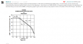
https://www.ti.com/lit/an/sloa068a/sloa068a.pdf The authors do not seem to understand PSRR measurement (as it is defined by their Power Management Products group.) They describe PSRR as we would describe DC CMR. Maybe Bonnie Bell should have a talk with them.Jack can you kindly send me a link to that app note?
I used the setup described in the Texas Instruments application note, grounded the emitters (each separately) via 1,000 uF Nicchicon Muse caps. (I read some papers on balanced amplifier measurements, but they mostly deal with microwave). Used AD8512 for the servos:

Jack, If I am reading your graph correctly the 1kHz spot noise is 200pV/rt Hz or approx 30nV RMS wide band which seems about 90pV/rt Hz too low - ie too good.
If you just short the inputs to ground with caps but leave nothing connected across the +- inputs, the gain of the front end is effectively 1 differentially.
I think a more realistic way to look at this will be to connect a 3.3 Ohm MF R across the inputs using the gain as 2*(Rcollector/Rsource+re') where re' = .026/Ie for the front end gain gain and get an output reading. Then calculate the thermal noise of the 3.3 Ohm R and subtract it - what you are left with is the amplifier thermal noise only.
Are you using a bal>unbal amp at the output? if yes, you will also have to factor that gain in as well.
Here's how I did the X-Altra MC/MM noise measurement
Attachments
Last edited:
The graph reads 300pV/rtHz instead of 200 at 1Khz.Jack, If I am reading your graph correctly the 1kHz spot noise is 200pV/rt Hz or approx 30nV RMS wide band which seems about 90pV/rt Hz too low - ie too good.
If you just short the inputs to ground with caps but leave nothing connected across the +- inputs, the gain of the front end is effectively 1 differentially.
I think a more realistic way to look at this will be to connect a 3.3 Ohm MF R across the inputs using the gain as 2*(Rcollector/Rsource+re') where re' = .026/Ie for the front end gain gain and get an output reading. Then calculate the thermal noise of the 3.3 Ohm R and subtract it - what you are left with is the amplifier thermal noise only.
Are you using a bal>unbal amp at the output? if yes, you will also have to factor that gain in as well.
Here's how I did the X-Altra MC/MM noise measurement
Hans
You are correct. It starts at 100 - my bad.
I still think the noise should be measured using a more conventional approach to confirm it.
Good to see it is in the ball park though. Nice work Jack.
I still think the noise should be measured using a more conventional approach to confirm it.
Good to see it is in the ball park though. Nice work Jack.
Connect a 3.3ohm, then a 33ohm, then a 100 ohm and see if the results are consistent (Gain decreases, source noise increases, etc...)
What makes me a little suspicious is the total absence of any mains frequency and harmonic components. Not even a mumetal double shielding can't completely avoid these, unless the lab is in the middle of Mato Grosso,
What makes me a little suspicious is the total absence of any mains frequency and harmonic components. Not even a mumetal double shielding can't completely avoid these, unless the lab is in the middle of Mato Grosso,
Last edited:
Back to the salt mine.
FWIW, the auto settling TLC4502 is noisy.
One can select the output impedance of the AP analyzer such that the parallel impedance of the source does not materially affect the analysis.
FWIW, the auto settling TLC4502 is noisy.
The so-called sanity test. I used it to check my math with Sam's excellent 1000x LNA (as the doctor ordered) -- QuanTech recommended the same. Quan-Tech has gone to a better home.Connect a 3.3ohm, then a 33ohm, then a 100 ohm and see if the results are consistent (Gain decreases, source noise increases, etc...)
What makes me a little suspicious is the total absence of any mains frequency and harmonic components. Not even a mumetal double shielding can't completely avoid these, unless the lab is in the middle of Mato Grosso,
One can select the output impedance of the AP analyzer such that the parallel impedance of the source does not materially affect the analysis.
"unless in the middle of Mato Grasso" or in Blaricum in the Netherlands for that matter.Connect a 3.3ohm, then a 33ohm, then a 100 ohm and see if the results are consistent (Gain decreases, source noise increases, etc...)
What makes me a little suspicious is the total absence of any mains frequency and harmonic components. Not even a mumetal double shielding can't completely avoid these, unless the lab is in the middle of Mato Grosso,
Repeatedly when measuring just on the top of my desk, I have no 50Hz anomalies, without any shielding with cans in cans, but always battery fed, see one example in the attachment for a current amp.
I had to think twice when I read that Jack had placed large caps par. to the emitter resistors, but this seems like a smart way of avoiding to measure with a simulated Cart resistance and then recalculate what the bare amp noise will be without Cart like you suggest with 3.3R and 33R , thereby assuming that current noise with these low resistances is insignificantly contributing to the noise production.
Looking at the noise replacement circuit in the attachment, it becomes clear that paralleling a large Cap to RE will give a direct and immediate result, without having to calculate anything, quite clever indeed IMO.
Hans
Attachments


Someone, If my memory serves me well it was LuckyDog, tried to measure distortion with various levels of DC current through the Cart.Question: does DC through the coil cause distortion? It is not a reciprocal motor, but if you had a DC current flowing thru the coil in a relatively strong mag field, how would that impact the output signal? Zero impact, negligible or something else? Would it cause 2nd harmonic distortion?
Although in this case it was an MM Cart, he could not find a shred of difference in THD or FR for the various injected DC currents.
Hans
https://www.jedec.org/standards-documents/dictionary/terms/supply-voltage-rejection-ratio-ksvrhttps://www.ti.com/lit/an/sloa068a/sloa068a.pdf The authors do not seem to understand PSRR measurement (as it is defined by their Power Management Products group.) They describe PSRR as we would describe DC CMR. Maybe Bonnie Bell should have a talk with them.
Maybe we audio types are a bit sloppy with terminology.
Jan
Attachments
Although in this case it was an MM Cart, he could not find a shred of difference in THD or FR for the various injected DC currents.
Typical MM cartridges have thousands of windings, perhaps 10 thousand or so. 300nA bias current x 10,000 = 3mA-turns total.
Say the winding is approximately a solenoid of length 5mm, 3mA-turns is 0.6A/m magnetomotive force, giving around 0.8µT for air-cored, or perhaps 2000 times as much for a laminated core, around 2mT. This is small compared to the flux densities that cores can handle in their most linear range.
Looking at the normal size of signals, 10mV output for a 10000 turn coil means a flux variation of the order of 1µWb/s, or at 1kHz a flux signal amplitude around 0.16nWb, which assuming a magnetic circuit cross-section of 10mm^2 would be 16µT - so definitely small signal regime.
But the permanent magnets themselves could be generating many mT into the core too, I'm not sure a small offset in the DC field is likely to matter, but I'm making a lot of assumptions about the coil and core geometry and magnetic circuit.
One possibility is that a cartridge might be phased so that a DC bias on both L and R leads to a strengthening of flux on one side and weakening on the other, which might be an issue, but given the signal is a change in flux due to position of a permanent magnet I'm not sure this would make a difference - the DC magnetic conditions basically shouldn't affect the AC signal as only changing magnetic field induces signal.
If that's the case its good to know.Someone, If my memory serves me well it was LuckyDog, tried to measure distortion with various levels of DC current through the Cart.
Although in this case it was an MM Cart, he could not find a shred of difference in THD or FR for the various injected DC currents.
Hans
Jack can you put up a sketch of your measurement set-up. I am struggling to see how the AP is calculating the input referred noise, since the gain with the caps across the emitter resistors is very high
Just to explain, this is not an FFT, but an analog analyzer with a 5th order bandpass filter. Divide by the filter factor -- as described by Jung in his 1995 articles "Regulators for High Performance Audio". Connections are to the balanced inputs of the analyzer via very short length of either RG174 or shielded twisted pair. I use the Costco Christmas Cookie tins!What makes me a little suspicious is the total absence of any mains frequency and harmonic components. Not even a mumetal double shielding can't completely avoid these, unless the lab is in the middle of Mato Grosso,
- Home
- Source & Line
- Analogue Source
- Low noise Balanced MC Pre