
Cats,
On the 8mm x 100mm x 100mm Panzerholtz sample in the post above, I get good damping (0.4 and better) up to about 500 hz. Above that, it reduces to lower values like 0.2, etc. Does that seem about right?
I'm intending for it to be a benchmark for other combinations.
Hugh
On the 8mm x 100mm x 100mm Panzerholtz sample in the post above, I get good damping (0.4 and better) up to about 500 hz. Above that, it reduces to lower values like 0.2, etc. Does that seem about right?
I'm intending for it to be a benchmark for other combinations.
Hugh
Hi Hugh
I get about 0.43 from your traces, after correcting for values above 0.3, or 0.45 before correction. I would expect higher damping at higher frequencies, not lower.
I get about 0.43 from your traces, after correcting for values above 0.3, or 0.45 before correction. I would expect higher damping at higher frequencies, not lower.
So... almost finished plinth acrylic-cheapboard-acrylic for my Elac 50h2... any recommendation regarding 3 vs 4 feet ? Recommendation regarding placement, avoid tonearm or use this area etc?
I was thinking since the idea is to use the properties of the sandwich to absorb, control vibrations, the best thing would be to put 4 feet in all four corners of the plinth.
I was thinking since the idea is to use the properties of the sandwich to absorb, control vibrations, the best thing would be to put 4 feet in all four corners of the plinth.
So... almost finished plinth acrylic-cheapboard-acrylic for my Elac 50h2... any recommendation regarding 3 vs 4 feet ? Recommendation regarding placement, avoid tonearm or use this area etc?
I was thinking since the idea is to use the properties of the sandwich to absorb, control vibrations, the best thing would be to put 4 feet in all four corners of the plinth.
I follow this thread hoping to get to a revelation at some point. i will build a new plinth for my Lenco at some point, i use my own build LTA.
So i read and absorb other peoples ideas.
I intend my sub plinth (rigid wall shelf sand box etc) to have minimum energy in it that is coming from the room side, and the record deck and plinth side tries to absorb to the maximum as far away from the cartridge as possible anything that is coming from the cartridge.
Based on that I believe the answers to your questions depend on many things, but;
It sounds to me that the plinth you describe is the only absorbing/damping medium and you don't want anything in terms of vibration etc coming up into it if you can avoid that, so i would go three mounts that are similarly loaded by the mass and as non transmissive as possible and spaced as far away from the T/A as possible to allow your plinth to absorb and damp as much as possible.
However, i may be wrong and there will be factors i dont know about your set up that affects things as well!
Interested to see and hear other input.
M
@Mike56
Thanks for sharing... I will post some pics soon. Hope this weekend I can finish with RB250 fixing to the new plinth...
Thanks for sharing... I will post some pics soon. Hope this weekend I can finish with RB250 fixing to the new plinth...
So... almost finished plinth acrylic-cheapboard-acrylic for my Elac 50h2... any recommendation regarding 3 vs 4 feet ? Recommendation regarding placement, avoid tonearm or use this area etc?
I was thinking since the idea is to use the properties of the sandwich to absorb, control vibrations, the best thing would be to put 4 feet in all four corners of the plinth.
I assume you mean chipboard, although I like the term 'cheapboard', covers all bases!🙂
Just a note, vibrations are not absorbed, the energy which causes the vibrations is transformed into heat energy by the damping mechanisms acting.
Always use four feet (or more). If the panel is 'free' around its edges, use one foot in the middle of the front and back, and two more in the middle of each side, as near to the edge as possible. If the edges are 'clamped', then anywhere near the edges will do.
People will suggest three feet, but that only works if your surfaces are very uneven, as in a rustic cattle shed. More than four are useful in some circumstances, but the 'free' or 'clamped' scenario still applies. I have six under one of my turntables. four in the 12, 3, 6, 9 position, and two in the middle of the panel.
You may find this useful, blue areas least vibration, red area most (for free edge panels):
 ffff abs first mode by cats squirrel,
Last edited:

DF vs Frequency
Ok, I'm disappointed I was unable to match your results for DF at higher frequencies. I'll try again on 20mm Panzer and fuss a little more over the pulses I select.
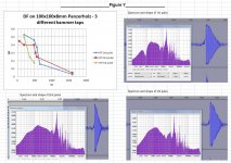
I'm posting this for another purpose. Figure Y shows the DF vs. Frequency for 3 different pulses. I selected a variety rather than subjectively choosing "good" ones.
What we get is a bit of variety in the DF results. The first 2 are good up to nearly 500 hz. The third drops off after 200 hz.
When I test the Acrylic/MDF/Acrylic combinations I'm trying to be more fussy about the pulse shapes. But I'm getting an even wider range of DF values vs. frequency.
It may be a good thing, but I'm finding it a bit disturbing. Maybe this Acr/MDF/Acr combination will be very dependent on the type of outside disturbances and music content compared to Panzerholz.
As a sanity check, I pulled up the files from a much earlier post. It was 1/4" Acrylic-1/2" Acrylic -1/4" Acrylic with Ductseal between the layers. So far, much more consistent and the DF is looking better at higher frequencies. I may be going for a final build more like that.
Will try to make time to post more graphs.
Hugh
I would expect higher damping at higher frequencies, not lower.
Ok, I'm disappointed I was unable to match your results for DF at higher frequencies. I'll try again on 20mm Panzer and fuss a little more over the pulses I select.
I'm posting this for another purpose. Figure Y shows the DF vs. Frequency for 3 different pulses. I selected a variety rather than subjectively choosing "good" ones.
What we get is a bit of variety in the DF results. The first 2 are good up to nearly 500 hz. The third drops off after 200 hz.
When I test the Acrylic/MDF/Acrylic combinations I'm trying to be more fussy about the pulse shapes. But I'm getting an even wider range of DF values vs. frequency.
It may be a good thing, but I'm finding it a bit disturbing. Maybe this Acr/MDF/Acr combination will be very dependent on the type of outside disturbances and music content compared to Panzerholz.
As a sanity check, I pulled up the files from a much earlier post. It was 1/4" Acrylic-1/2" Acrylic -1/4" Acrylic with Ductseal between the layers. So far, much more consistent and the DF is looking better at higher frequencies. I may be going for a final build more like that.
Will try to make time to post more graphs.
Hugh
Attachments
not sure I understand the diagram. The larger rectangle and feet positions are fine, but does the 'turntable' sit on the rectangle, or is it part of it? Can you draw a side view?
There is a “hole” as per Elac mounting template and turntable sits on and is screwed with 4 screws in the corners to the big rectangle sandwich board plinth.
think I understand now, so that should be OK. Is the arm mounted on the plinth (as described) or will it have its own arm pod?
the Rega/cart do sound better when mounted on a separate arm pod. And it is possible to match the mechanical impedance of the arm to the arm board, so transferring any vibrations in the arm (base) quantitatively to a highly damping arm board.
Continuing from a few posts above...
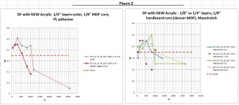
These DF (Hammer tap) tests were performed using NEW Acrylic instead the old weathered pieces I have on hand. The panels are 4"x4" or 4.5"x4.5". Thicknesses of the outer Acrylic layers were 1/4" or 1/8".
One of the cores is 1/8" MDF trimmed from a thicker piece. The other two are "Hardboard" which looks like MDF, but just a bit more dense.
The left side of Figure Z uses a stiff adhesive - Lepage's PL. The Acrylic layers are twice as thick as the core (unlike previous efforts). Note that there's quite a different in the calculated Damping factor for the two different pulses. The Light Brown trace stays over 0.35 DF up to 1khz.The Dark brown trace is good just over 500 hz. I'm sure if I examined more pulses that spread would be even greater.
That's a bit discouraging, but I suppose this combination (scaled up to a full plinth with 2x 1/2" outer layers and 1/4" MDF Core) MAY still work OK as a plinth.
The Green traces on the right side of figure Z are a repeat of the above except the adhesive is the softer Maxstretch adhesive. The core is Hardboard. It seems like maybe the the DF results may be more repeatable in the 800 to 1000 hz area (light green vs. Dark green). Repeating with more pulses would be needed to confirm.
When filtering the pulses at low frequencies, I did notice that the "logarithmic decay" was very hard to get anywhere near straight. DF of 0.4 and above could just as easily have been called 0.3 . So, there's a slight hint that the Maxstretch (or Hardboard?) allows the low frequency DF to get a little mushy.
The blue traces on Figure Z use Maxstretch adhesive again. The layers are all 1.8". Again the two traces show poor repeatability.
Then, I reworked some old results from a much earlier post. It was three layers of acrylic with Ductseal in between. It seems very good for DF and repeatability. More later on that.
Hugh
Attachments
3 Layer Acrylic with Ductseal
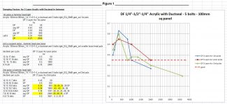
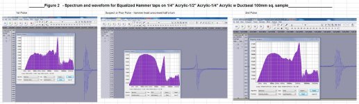
This one is described as a full sized plinth on page 26 post 252. The test sample (100mm x 100mm) is 1/2" Acrylic sandwiched between 1/4" Acrylic layers. GB Ductseal is in between. Bolts in the corners and center hold it together because Ductseal is not an adhesive. So, once again this does not meet the definition of CLD.
Figure 2 shows the waveforms and spectrums for three Hammer taps. The ones labelled as 1st and 2nd are subjectively deemed "good". In the middle one, the tip of the hammer had worked it's way loose. I'm calling this the bad pulse.
Figure 1 shows the Damping factor estimate at various frequencies for each pulse. I did the last one this morning and found the repeatability is not quite as nice as I was expecting. But the overall results are better than anything else I've tested.
I suspect that other thicknesses of layers would also be fine. I'll likely go with 1/4, 1/2,1/4 inch just because I have some 1/2" pieces on hand.
I'm also intending to try GE Maxstretch (and no bolts) as well as Greenglue (with nylon bolts). But I will to shelve project this for a few months. Other activities coming up.
Hugh
Attachments
The blue traces on Figure Z use Maxstretch adhesive again. The layers are all 1.8". Again the two traces show poor repeatability.
Correction... That should read " The layers are all 1/8".
- Home
- Source & Line
- Analogue Source
- DIY CLD Plinth Design--A measured Approach