Cats,
Lucky for me this is not my day job eh?
Thanks for your feeedback. I do appreciate it even if my response here might suggest otherwise. Here's what I was attempting to accomplish (and more questions)...
The use of the beads is an attempt at getting exactly the same force with each blow so that the levels for each material can be fairly compared. For most, I do have hammer taps in the same Audacity files. I agree they produce a more representative spectrum. There's just more variation in magnitude in my hands. I need a robot.
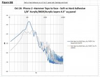
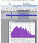
Figure QQ is a Hammer Tap rework of Figure Q with a similar conclusion in my view. The softer Maxstretch adhesive allows resonance at lower frequencies. The PL Adhesive allows more vibration above 500 hz. It almost looks as if each expends the same overall amount of energy - just differing spectrums.
Later, I'll post another test on an actual Turntable that suggests why this may not matter. It'll be Hammer taps.
Lucky for me this is not my day job eh?
Thanks for your feeedback. I do appreciate it even if my response here might suggest otherwise. Here's what I was attempting to accomplish (and more questions)...
The use of the beads is an attempt at getting exactly the same force with each blow so that the levels for each material can be fairly compared. For most, I do have hammer taps in the same Audacity files. I agree they produce a more representative spectrum. There's just more variation in magnitude in my hands. I need a robot.
Figure QQ is a Hammer Tap rework of Figure Q with a similar conclusion in my view. The softer Maxstretch adhesive allows resonance at lower frequencies. The PL Adhesive allows more vibration above 500 hz. It almost looks as if each expends the same overall amount of energy - just differing spectrums.
Later, I'll post another test on an actual Turntable that suggests why this may not matter. It'll be Hammer taps.
Attachments
Your recent use of a moving magnet cartridge is not, in my opinion, a good thing. It shows vibrations in two directions at once, confusing the issue.
And placing the test apparatus on the test piece is a no-no. The test piece must be suspended. All this will then provide data from which objective conclusions can be made.
In post 374, Figure J (1/2" x 18"x14" Acrylic ), some of those narrow spikes above 500 hz look intimidating. The use of a cartridge and Phono stage (RIAA curve) is intended to show whether they matter.
I'm recording the Phono output in Stereo and (I believe) Audacity is summing left and right in the spectrums. True? If so, I think the sum is equivalent to vertical deflection.
Setting the piece on 3 feet produces different harmonics than suspending it. Placing an off center mass (knob) changes it even more. I think it may also mess up the damping at low frequencies with respect to the suspended panel. I'm attempting (with questionable success) to mimic a Turntable as opposed to panel.
Re " And placing the test apparatus on the test piece is a no-no. " Are you referring to the structure holding the Cartridge? It has a pivot at the back like a very cheap tonearm. Is it the structure holding the pipes? That one does not contact the plinth - only the white speaker stand below it.
Questions:
Why does a bead strike produce a different spectrum than a decent hammer tap? Is it somehow an inferior approximation of an Impulse? Is it something about the materials being struck (hysteresis or similar)?
Hugh
thanks for the explanations. However, I think you are getting ahead of yourself. In the beginning, one has to assess a panel of material/s to estimate their damping qualities. That is all. Once one finds a suitable material/s, then one can progress to other things.
I don't believe you have investigated the damping thoroughly enough. What is need is a material (or laminate) which has a damping factor approaching 0.4, not an easy task.
You may also find this interesting. Note the positions are arbitrary, just to help clarity:
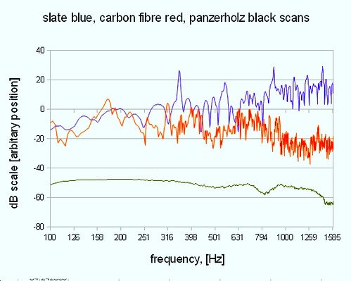 fft comparison slate CF panzerholz by cats squirrel
You may find this table interesting:
 damping table by cats squirrel
The damping ratio is in %, so 1 is equivalent to a damping factor of 0.02, then 0.1, 0.2, 0.4 and finally 0.6. It is then easy to see that above 0.4, any increase in damping is slight.
I don't believe you have investigated the damping thoroughly enough. What is need is a material (or laminate) which has a damping factor approaching 0.4, not an easy task.
You may also find this interesting. Note the positions are arbitrary, just to help clarity:
fft comparison slate CF panzerholz by cats squirrelYou may find this table interesting:
damping table by cats squirrelThe damping ratio is in %, so 1 is equivalent to a damping factor of 0.02, then 0.1, 0.2, 0.4 and finally 0.6. It is then easy to see that above 0.4, any increase in damping is slight.
Last edited:
Also, were those pieces measured with the Analog Devices Accelerometer or the more expensive one you mentioned a while back?
Yes, that is very interesting. Were those graphs from 100mm x 100mm pieces? How thick?
Thanks
can't remember exactly, but would be around those figures, I tended to specify 100mm x 100mm if possible. Slate I bought from Delabole quarry directly. Carbon fibre came from a University, Panzerholz from a Luthier in France. As with most materials, they can vary a bit! Thicknesses unknown, but not thick!
Note, comparison is only to show vibrations, not comparative losses.
B
Also, were those pieces measured with the Analog Devices Accelerometer or the more expensive one you mentioned a while back?
With the cheap Analog Devices Accelerometer, ADXL335 with 3.0 volts.
Note, the ADXL337 is the latest offering in this series, which has a slightly better frequency response.
Last edited:
thanks for the explanations. However, I think you are getting ahead of yourself. In the beginning, one has to assess a panel of material/s to estimate their damping qualities. That is all. Once one finds a suitable material/s, then one can progress to other things.
I don't believe you have investigated the damping thoroughly enough. What is need is a material (or laminate) which has a damping factor approaching 0.4, not an easy task.
.
Cats,
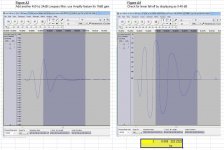
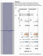
Lately I've been using the FFTs to decide what's well damped. But, here's one example of a Damping Factor calculation by Logarithmic Decrement. The steps are described for some "scrutiny". It may also help anyone else crazy enough to try this. It's a tough one. DF is around 0.6.
After I thought I was "done" I realized I should have tried other filter combinations. If I reworked it, I think it would still be well over DF = 0.4.
Figure A is from an earlier post. It's the 4.5" x 4.5" Acrylic/MDF/Acryic with PL Adhesive Mini Plinth from an earlier post. (1/8" layers). The FFT has been equalized as decribed earlier by Cats Squirrel (this thread I hope). I picked the moderate, wide 330 hz hump as my resonance. Alternately, I could have gone for the one around 180 hz. Similar hump - similar results?
Figures A1 through A5 describe the steps to measure Damping Factor by Logarithic Decrement. At the end, I realized I'd captured a combination of the 330 and 180 hz, so it could use more polishing. The point is, this is the method I'm using to compare materials. Does it look reasonable otherwise?
A 100mm x 100mm combination of 12mm Acrylic /14mm MDF /12mm Acrylic shows a DF of about 0.35. I'm thinking that's probably the ballpark for a real plinth made from these materials.
The Mini Plinth in Figures A-A5 suggests a wonderful DF, but it's made from weathered Acrylic.
Hugh
Attachments
I should have mention the adhesive in this line...
A 100mm x 100mm combination of 12mm Acrylic /14mm MDF /12mm Acrylic using WOOD GLUE is damped at about 0.35.
(Maybe it's the glue, but I don't think so).
H
A 100mm x 100mm combination of 12mm Acrylic /14mm MDF /12mm Acrylic using WOOD GLUE is damped at about 0.35.
(Maybe it's the glue, but I don't think so).
H
Scratch that last statement. I just re-checked the "100mm x 100mm combination of 12mm Acrylic /14mm MDF /12mm Acrylic using WOOD GLUE" in more detail.
I get DF of 0.46 for humps at 1000, 600 and 200 hz.
Hugh
I get DF of 0.46 for humps at 1000, 600 and 200 hz.
Hugh
Ha! I just measured the DF of the trace of that which you tested and posted, and I obtained a DF of 0.46 (accounting for answer above 0.3). 🙂
If this is really a true reflection of the material you have made, then you have truly made progress. Well done.
Now repeat the experiment with several pieces of acrylic/mdf/acrylic PVA glue, and hopefully obtain the same results (or very similar!). Also try different thicknesses, and a one sided one (acrylic/mdf/no second layer).
When applying filters, use the same frequency for high pass and low pass. Also, use no more than six hammer taps to work on, and cherry pick the best to obtain the six.
Last edited:
Thanks Bryan.
I did try a single layer of Acrylic with something else. I'll dig it up later and post it. The DF was not near 0.4 as I recall.
Post 411 is exactly that - acrylic/mdf/acrylic PVA glue (Elmer's Wood Glue). Did you mean PVB glue?Now repeat the experiment with several pieces of acrylic/mdf/acrylic PVA glue, and hopefully obtain the same results (or very similar!).
I did try a single layer of Acrylic with something else. I'll dig it up later and post it. The DF was not near 0.4 as I recall.
By the way, I've been viewing Wood Glue as just a temporary adhesive for test purposes. I haven't tried, but I think it would let go of the Acrylic fairly easily. Am I wrong in that thinking?
No, I mean repeat exactly what you have done with acrylic and mdf, several times. Then vary the thicknesses.
One cannot rely on just one result, however much one may like it! Although I worked for a multi-million pound business that have accepted just one result, because it was so good! They didn't last long, though... fortunately, I knew what was what, and left before the brown smelly stuff hit the rotating wind machine.🙁
One cannot rely on just one result, however much one may like it! Although I worked for a multi-million pound business that have accepted just one result, because it was so good! They didn't last long, though... fortunately, I knew what was what, and left before the brown smelly stuff hit the rotating wind machine.🙁
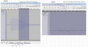
When applying filters, use the same frequency for high pass and low pass.
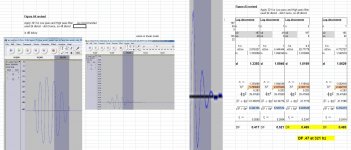
Just in case anybody wants to see what this does, see the attached revisions to figures A4 and A5 from post 409. I picked 321 hz for the filters. I suspect if I'd used 180 (lower hump) the DF would be lower.
Thanks for that advice Bryan. An thanks for recommending Acrylic/MDF/Acrylic as a combo.
Hugh
Attachments
I have not stopped visiting this thread, as the methods being investigated are of interest to myself, as I will in the not too distant future commence producing a few versions of Plinths Structures for comparison.
As a layman on these types of experiments being undertaken, is the latest reading produced by both Hugh and Bryan approaching the results produced for Densified Wood Board when under test conditions ?
During the reading about the Tier Construction of Acrylic/MDF/Acrylic , my thoughts were pondering the idea of rebating the MDF and infilling with a a very cheap to produce mixture that will become a Oil Saturated Sand/Bentonite Mixture to see how this addition will impact on the Damping.
The idea has been born originally from a friend who proposed I look into
Saturated Sand Damping, when assessing the material, for use as a damping method, the immediate idea come to the surface, of bedding into this mixture the upcoming and 'in the making Kaneta Design Technics SP 10'.
The Bearing and Stator Mounting Metal Formed Bowl will be seated into a Material such as Densified Wood, which I see as an improvement over the original metal chassis, combining the Chassis and Plinth into a singular amalgamated role.
The exposed Bowl on the underside and Protrusion from the Bowls Base for housing the Platter Spindle could then be submerged into an Oil Saturated Sand / Bentonite Mixture.
It seemed this might prove quite satisfactory as a cost effective method to Damp/Dissipate energy transferred from the entirety of the assembly.
John,
I think Cats squirrel is the one to comment on the Panzerholz vs. this latest stuff.
At the risk of contradicting myself again, here's my 2 cents at this point...
Is suspect that the harder glues for Acrylic/MDF/Acrylic will be better for Low Frequency damping. I'm intending to post another Mad Scientist test on a Turntable that suggests the higher frequencies don't get to the Cartridge. So, efforts to damp Acrylic/MDF/Acrylic further may actually be worse at low frequencies.
Of course, I'm ahead of myself here. Be prepared for another Flip-flop later.
Hugh
Also try different thicknesses, and a one sided one (acrylic/mdf/no second layer).
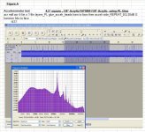
That's looking like a really good idea. I have an older file for 1/8" Acrylic outer layers and 1/4" MDF as the Core. It's a cheap brand of PVA Wood glue on this one.
I get Damping factors of .4 or more at at 72, 177 and 331 hz.
Then I get LOW DF's of around .15 at 550 and 866 hz. I wonder how the 1/8" core compares to this.
Question...
The spectrum is for just one pulse, but typical for the group. Is that big dip at 1443 Fc by any chance?
Attachments
John,
efforts to damp Acrylic/MDF/Acrylic further may actually be worse at low frequencies.
Hugh
Let's refine that a bit...
Efforts to use CLD (e.g. Greenglue) to damp Acrylic/MDF/Acrylic will likely diminish LF Damping. Other damping techniques may help. I really don't know.
H
- Home
- Source & Line
- Analogue Source
- DIY CLD Plinth Design--A measured Approach