Learning Mode
Seems like a great book: the explanation of electron drift is the most comprehensive I have seen. That, and experiments and simulations...although I have my reservations about Falstad circuit sim... seems to give different results from time to time.
I could simply set the source as DC current, not AC, at the maximum input level which I have measured as :
Source zero volume to max volume (Multi-meter in AC Voltage mode) and adjust the circuit that way. In any case, the minimum and maximum output voltages are the important thing, anything in between is the transistor's responsibility to be nice and linear.
+ 1000 🙂
That was my Physics Textbook when I started studying Engineering in 1969 , hesitated...
You will learn how/why through experiments, they are chock full of them.
Seems like a great book: the explanation of electron drift is the most comprehensive I have seen. That, and experiments and simulations...although I have my reservations about Falstad circuit sim... seems to give different results from time to time.
I could simply set the source as DC current, not AC, at the maximum input level which I have measured as :
Source zero volume to max volume (Multi-meter in AC Voltage mode) and adjust the circuit that way. In any case, the minimum and maximum output voltages are the important thing, anything in between is the transistor's responsibility to be nice and linear.
Laptop: 0.00 mV to 100 mV
Mobile Phone: 0.00 mV to 70 mV
DVD Player: 2 Volts to 9 Volts (Multi-meter in AC Voltage mode)
DC mode - a few millivolts.
THANKS for actually building it, doubly so for DOCUMENTING the experiment.what I type here is true, I took some time, took some components and Build your Circuit according to your last Simulation. Exactly that way,
I used another Transistor which fits better for a CLASS A
I used Double Voltage because with 9 Volts you will never hear any sound out of your Speakers.
I used Huge Resistors with a resistance of 7.7 Ohm and since you are using 5% Components, the Resistor is just a good match. Tolerance is within this 5% it's even less.
Also I used a High Grade Cap at the input with 10Uf 63 Volts Non Polar.
I hooked up Oscilloscope and Function Generator voltmeter Ohm Meter and all what one uses to test a circuit to get REAL MEASUREMENTS OUT OF IT, and not DREAMS
Simulators are fine to *PRE* test options and save a lot of time, but then you must go through the Real Deal.
For example, simulator resistors do not smoke, supplies keep steady, do not burn if shorted,etc.
So check out the pics, and then start with the BASICS learn them.
Forget to talk about Distortion, rather inform yourself what an Resistor Array does, what an Resistor divider is meant for and that a LOAD Resistor for the COLLECTOR of a NPN Transistor isn't a equivalent for a SPEAKER and that the Circuit you try to build lacks of at least 2 Components.
At the Output you need to add a OUTPUT CAP to block DC off from the output signal
at the input it would take a BASE GND RESISTOR to lock input impedance to some certain level..
Good luck
Regards
Chris Hess[/QUOTE
Thanks again.
Regarding your circuit post # 97:
You have not got a potential divider on the base, have you?
You need to step back to the original 4-resistor circuit. This is known as the "basic class A bias" for a reason.
You want to run at 9V. You need an 8 ohm speaker. The collector load needs to be about 8 ohms. Let the emitter sit at 1V so that the emitter resistor can set the current properly.
The collector voltage then has to swing from 1V to 9V (nominally, although the speaker load and emitter voltage will reduce the available swing) so at a guess the collector needs to sit at 5V. That leaves 9-5V to drop across the collector load resistor.
If that is 8 ohms, what current does the transistor pass?
(Clue: Ohms law says 5/8A).
Now what resistance do you need in the emitter?
(Clue: Ohm's law says 1/(5/8)=8/5 ohm). A 1.5 ohm would work. at reduced stability a 1 ohm resistor might also, but that puts the emitter voltage down to 5/8V. Which is about as low as we dare go.
Now choose your transistor.
It's got to be able to pass at least the standing current plus any signal-induced variations. Let's say a 4A device. Take your TIP41A. It's max current is 7A so seems to meet requirements. What is its gain?
(Clue: look up the datasheet. Min. 30 at 300mA when Vce=4V. Dropping to 15 at 3A. This is where you need to know more about transistors. Running at 5/8A means the gain could be perhaps 25.)
What base current does this mean?
(Clue: Ib=Ic/hFE. hFE is the forward gain also known as beta).
Now what current do your base bias resistors need to conduct?
(Clue: in my previous post I suggested 5x Ib.Clearly some current will divert into the base - you've learned that much. So if the bias resistors are R1 and R2 make R1 conduct 6x Ib and R2 5xIb then things will work out as long as you know the voltage to set the base to.)
What voltage is that?
(Clue: to get as much power out as possible we need the emitter resistor not to be too large. Let's go for 1 ohm. Emitter voltage will be 5/8 volt =0.6V. For a power transistor conducting a bit of current the base-emitter voltage could be nearer 0.7 than 0.6V. So Vbe=1.3V)
Now you have the bias voltage you need and the current you need the resistors to pass.
Can you complete the circuit?
Then can you answer whether this has achieved a worthwhile result?
Take some time to study hpro's messages and images. That's a lot of useful info for you.
Well done to hpro for actually constructing the circuit!
Last edited:
Replies to hpro
I lacked the basics - understanding the voltage divider, will share that later... incorrect understanding of voltage divider.
OK
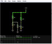
My question about the resistor array was why use two resistors? I went to the circuit sim and then found out by simulation that it is not possible to make the voltage drop anything other than 5V when only one resistor is connected.
I got my question answered with the circuit sim: please look at the two 25 Ohm resistors in the attached circuit: The current flowing through each resistor is different, the voltage across each resistor is different: In my mind, I thought they would be equal. I had forgotten my physics.
Output cap: I agree.
Thanks Chris for building the circuit. I think it is now my turn to build the circuit and find out how this should work, now that I realize the need for four resistors instead of two.
Hi BasicHIFI1
I think you do not understand what everyone here tries to say and teach you.
Go with the FUNDEMENTAL BASICS. This is were you show a big LACK of.
I lacked the basics - understanding the voltage divider, will share that later... incorrect understanding of voltage divider.
And just that you see that this what I type here is true, I took some time, took some components and Build your Circuit according to your last Simulation. Exactly that way,
...
OK
I hooked up Oscilloscope ...
So check out the pics, and then start with the BASICS learn them.
Forget to talk about Distortion, rather inform yourself what an Resistor Array does, what an Resistor divider is meant for and that a LOAD Resistor for the COLLECTOR of a NPN Transistor isn't a equivalent for a SPEAKER and that the Circuit you try to build lacks of at least 2 Components.
My question about the resistor array was why use two resistors? I went to the circuit sim and then found out by simulation that it is not possible to make the voltage drop anything other than 5V when only one resistor is connected.
I got my question answered with the circuit sim: please look at the two 25 Ohm resistors in the attached circuit: The current flowing through each resistor is different, the voltage across each resistor is different: In my mind, I thought they would be equal. I had forgotten my physics.
At the Output you need to add a OUTPUT CAP to block DC off from the output signal
at the input it would take a BASE GND RESISTOR to lock input impedance to some certain level..
Output cap: I agree.
Thanks Chris for building the circuit. I think it is now my turn to build the circuit and find out how this should work, now that I realize the need for four resistors instead of two.
Attachments
A solved circuit
I found a circuit that will work of 12V. Set up in Falstad and it works with 9V with the resistor values shown.
I got off to a wrong start with You Tube circuits.
The solved circuit is halfway down the page, I have printed it out for reference.
Common Emitter Amplifier – ALL ABOUT ELECTRONICS
By the way, the circuit sim needed a new scope added after the changes as the old scope showed below zero output signal (sign wave in negative territory).
Regarding your circuit post # 97:
You have not got a potential divider on the base, have you?
You need to step back to the original 4-resistor circuit. This is known as the "basic class A bias" for a reason.
.....
I found a circuit that will work of 12V. Set up in Falstad and it works with 9V with the resistor values shown.
I got off to a wrong start with You Tube circuits.
The solved circuit is halfway down the page, I have printed it out for reference.
Common Emitter Amplifier – ALL ABOUT ELECTRONICS
By the way, the circuit sim needed a new scope added after the changes as the old scope showed below zero output signal (sign wave in negative territory).
Attachments
If you work with that circuit and check against the explanation you found, you will start to progress.
You still need to understand what the capacitors are doing. They are separating the signal from the circuit so that the transistor is biased in its operating configuration and that the input and output don't change it.
The output capacitor disconnects the D.C from the collector so that there will be a sinewave on the output signal across the load resistor (1M) which will swing around zero, so will go negative. Not sure what you meant by your "sinewave in negative territory", but if the capacitors are initially uncharged there will be a charging current which alters the bias (and output) temporarily while they charge.
I think it will not work the way you draw it, Reason below
Hi
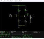
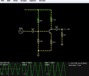
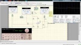
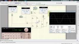
Taking your simulation onto my Simulator, then I get these Screens.
Remember, speaker impedance are 4 8 16 Ohms usually, but there aren't any with 1Mega Ohm.. *Your Output Resistor.*
So I simulated your design and what you see in these pics, that is what you got of that last of your simulation pictures.
Remember we talking about CLASS A here. I think you need to update your knowledge about Class A,
What also is, your Circuit has a 180 Degree Phase shift, which actually in nothing what someone wants. That's why I also simulated your Circuit without Phase shift.
Then also I simulated the Circuit with VCC 9.0Volts and also VCC12 Volts..
My advice to you: Go over it again with Speaker Load of 8 Ohms in mind and not 1MEGA OHM.
Again: in this screenshots you see your Circuit with all relevant
data it uses to work according to your drawing you placed in Post " Revised vertical scale on scope."
Check out the pics
Hi
Taking your simulation onto my Simulator, then I get these Screens.
Remember, speaker impedance are 4 8 16 Ohms usually, but there aren't any with 1Mega Ohm.. *Your Output Resistor.*
So I simulated your design and what you see in these pics, that is what you got of that last of your simulation pictures.
Remember we talking about CLASS A here. I think you need to update your knowledge about Class A,
What also is, your Circuit has a 180 Degree Phase shift, which actually in nothing what someone wants. That's why I also simulated your Circuit without Phase shift.
Then also I simulated the Circuit with VCC 9.0Volts and also VCC12 Volts..
My advice to you: Go over it again with Speaker Load of 8 Ohms in mind and not 1MEGA OHM.
Again: in this screenshots you see your Circuit with all relevant
data it uses to work according to your drawing you placed in Post " Revised vertical scale on scope."
Check out the pics
Attachments
-
 7. Sine None Inverting 12Volts 8 Ohms.jpg414.5 KB · Views: 112
 -
 8. Sine None Inverting 12Volts Open Out.jpg418.9 KB · Views: 99
 -
 6. Sine None Inverting 9V 8Ohms.jpg426.3 KB · Views: 102
 -
 5. Sine None inverting 9V Open Out.jpg414.9 KB · Views: 93
 -
 4. Sine Inverting 12 Volts Ohms Out 10mv.jpg416.8 KB · Views: 90
 -
 3. Sine Inverting 12 Volts Open Out.jpg417.3 KB · Views: 100
 -
 2. Sine Inverting 9Volts 8Ohms Out 10mv.jpg417.6 KB · Views: 232
 -
 1. Sine Inverting 9Volts Open Out.jpg420.9 KB · Views: 247
Yes, you’re right, the amp that he’s working with now (in simulation) cannot directly drive a loudspeaker. It’s a small signal amplifier stage. But we’ve had to back up a few steps and learn some basics first - which is far easier and more productive in the long run than trying to learn the same basics on something that does drive a loudspeaker. This circuit could easily be built on a breadboard and verified. Learn how and why it works. Then move on to more difficult things - like driving a loudspeaker.
A few thoughts on that circuit
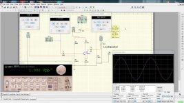
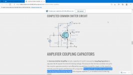
The Circuit you choose is a Input Stage Circuit of a Class A Amp.
You will not be able to drive a Loudspeaker directly. I highlighted a Sentence about that Circuit in the Screenshot I add. If you read all very carefully then you would know that this circuit is not suited for driving a loudspeaker..
In my prior Post please note that I made two Simulation on that circuit..
Once open, once with 8 Ohm Load. so that you can see the difference..
Here on this site are at least 100Schematics of Class A high Output Amps, to build.. So make search Class A Power Amp. Or just hit that LINK and start to build, I did already as well as many others and it will WORK,
And there are many Ways to configure that ..
Try it..
The next time you want to build an Amplifier, you need to decide what the Amp should do. A buffer, or a Power Amp.. there is a big difference with it..
Regards Chris
Thumbnail. Screenshot of the Link you posted.
I found a circuit that will work of 12V. Set up in Falstad and it works with 9V with the resistor values shown.
I got off to a wrong start with You Tube circuits.
The solved circuit is halfway down the page, I have printed it out for reference.
Common Emitter Amplifier – ALL ABOUT ELECTRONICS
By the way, the circuit sim needed a new scope added after the changes as the old scope showed below zero output signal (sign wave in negative territory).
The Circuit you choose is a Input Stage Circuit of a Class A Amp.
You will not be able to drive a Loudspeaker directly. I highlighted a Sentence about that Circuit in the Screenshot I add. If you read all very carefully then you would know that this circuit is not suited for driving a loudspeaker..
In my prior Post please note that I made two Simulation on that circuit..
Once open, once with 8 Ohm Load. so that you can see the difference..
Here on this site are at least 100Schematics of Class A high Output Amps, to build.. So make search Class A Power Amp. Or just hit that LINK and start to build, I did already as well as many others and it will WORK,
And there are many Ways to configure that ..
Try it..
The next time you want to build an Amplifier, you need to decide what the Amp should do. A buffer, or a Power Amp.. there is a big difference with it..
Regards Chris
Thumbnail. Screenshot of the Link you posted.
Attachments
Here on this site are at least 100Schematics of Class A high Output Amps, to build.. So make search Class A Power Amp. Or just hit that LINK and start to build, I did already as well as many others and it will WORK,
The FAOW requires a MOSFET, could you suggest one?
There are amplifier circuits posted here on this thread able to drive a speaker, using a BJT?
You really need to stop and review everything you've been told, and re-read that link you found to the one-transistor amplifier.
We could tell you what MOSFET you might use but many are suitable, and it won't help because you need to know how the work in greater depth, understanding things like threshold voltage and conductance to make a circuit work.
We have told you that you CAN make a single transistor BJT circuit drive a loudspeaker but it isn't simply a matter of connecting a speaker to the circuit in that article again because the output power is so low.
We've also suggested that once you realise that a single transistor is rarely used in practice because it has limitations you really need to look elsewhere.
Nelson Pass has several examples of simple circuits which do work, and you really should spend a while over on his site (and the thread on this site) to see what his circuits offer.
For about the simplest Class A circuit using BJT's which delivers useful power there are options for three transistors, maybe delivering 1-3W, or John Linsley Hood's 10W using just four.
Take a look at these options and try to understand how they work.
# 87 Connect 8 ohm / 50 W to the collector. The consumed current is 1A. Power consumption 24 watts. Big heatsink. Output power 1 W / 8 ohms.
@OldDIY
- that's possible, but again the OP keeps wanting to run everything from 9V.
That won't get him much power unless it is push-pull at least. Or very inefficient.
Something has to give - and so far it's our exasperation!
- that's possible, but again the OP keeps wanting to run everything from 9V.
That won't get him much power unless it is push-pull at least. Or very inefficient.
Something has to give - and so far it's our exasperation!
You really need to stop and review everything you've been told, and re-read that link you found to the one-transistor amplifier.
Yes am doing this - re-reading the posts from #1 and it makes more sense now.
When I tried out the single transistor setup from YT and it worked I was impressed and spent quite some time listening on it - single channel. I don't feel like listening to any other amplifier right now so my speakers have been silent for days...
#31
At least keep GROSS DC out of your speakers and stop watching those 1600W Extreme Bass projects built around a transistor pulled from a CFL lamp.
Stopped.
Last edited:
The FAOW requires a MOSFET, could you suggest one?
There are amplifier circuits posted here on this thread able to drive a speaker, using a BJT?
Have you tried to read all post of that thread FAOW?
There is plenty of explanation, finished circuits, the name of the MOSFET and more..
you will need to invest some time if you want to be successful...Without Time, you will not get anywhere.
"When I tried out the single transistor setup from YT and it worked I was impressed and spent quite some time listening on it"
... meanwhile, your 3F capacitor was slowly frying itself...
Suggest you do as hpro says. Look up the whole thread of FAOW.
... meanwhile, your 3F capacitor was slowly frying itself...
Suggest you do as hpro says. Look up the whole thread of FAOW.
"When I tried out the single transistor setup from YT and it worked I was impressed and spent quite some time listening on it"
... meanwhile, your 3F capacitor was slowly frying itself...
When I built one of those I didn’t bother with the capacitor. I just stuck a speaker in the collector lead of a 2SB407 and got sound out of it. A small DC bias in the VC isn’t the end of the world - it hurts that less than it does a 2.5 volt capacitor. You get a few tens of milliwatts, but it’s far from a real working amplifier.
My first “working” amplifier was an LM380 with the required handful of capacitors. Gotta start somewhere, and it’s not really a bad place to start.
- Home
- Amplifiers
- Solid State
- Simple Class A Amplifier Project