About power supply.
The best is with trafo, synchronous rectifiers and MLytic caps.
If you go for SMPS, I recommend this one.
It has very low noise, low footprint, not expensive and it was tested by me. It will work just fine with 2 x Q17 with 3 pairs. Go for +/-60V.
Regards,
Tibi
Hello Tiby,
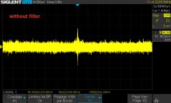
I have had a bad experience with low-end Chinese SMPS. I tested several of them and they burned out after a few weeks.
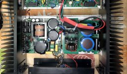
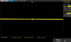
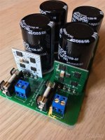
I am using Connex SMPS500 or SMPS600. I have 50V and 60v version. I also add in some cases an extra PI filter (3300uF on PSU + 10mH + 0R47 + 6800uF + 4.2uF MKP, resonance frequency at 19Hz).
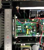
In my Quad enclosure, I have a 50v version.
First, I must know if the purple card fits in my enclosure. If not, maybe I can test your SMD version of the board if the SMD parts are already soldered. I can finish the rest.
For the necessary components, I expect an order to Mouser soon. I would take the opportunity to add what is needed for Q17.
Stef.
Attachments
Last edited:
Hi Tiby,
I've read one of the previous post.
What is the size of the violet board?
If it fit in my box, I have the habit to do manually this kind of holes under the PCB. I can test it with a Connex PSU.
Stef.
Hi Steff,
The Q17 PCB with a pair of final transistors has 102 x 71 mm.
At the end of this week I will post a BOM and a diagram with the drilling dimensions.
Hello Sorin,
The card should fit. I have room in length and the radiator is 85mm high.
Lots of holes to make and very precise position needed. 🙂
The easiest way would be to have a card with the power transistors at the end like the clone boards or the Tiby's SMD version.
Stef.
The card should fit. I have room in length and the radiator is 85mm high.
Lots of holes to make and very precise position needed. 🙂
The easiest way would be to have a card with the power transistors at the end like the clone boards or the Tiby's SMD version.
Stef.
Attachments
Last edited:
Steff,
But I have such a design with two pairs of mosfet transistors. see the first post on page 29 of this topic.
Unfortunately, time is not friendly to me ... I will barely make time to present the version with a pair of final transistors next weekend ...
But I have such a design with two pairs of mosfet transistors. see the first post on page 29 of this topic.
Unfortunately, time is not friendly to me ... I will barely make time to present the version with a pair of final transistors next weekend ...
Unfortunately, time is not friendly to me ...
We all have the same concerns. 😉
Regarding your PCB with the transistors at the end. Very nice and well thought out.
I wonder if it would not be a good thing to make a version with only two power MOSFETs and the dimension of the LJM board (and same location for the mounting holes). He sold thousands of them. There is going to be demand from those using this board.

Stef.
Last edited:
Hello,
I have 3 questions if you can answer me.
For the capacities (C15 / C16) on the power supply bus, what is the minimum acceptable value?
For the L1 coil of 1.2uH in radial or axial version, do you have any references?
For the speaker output. Do we need 2 separated pins (out speaker and GND) or can we share the same GND pin as in the real 450 design?
Thank you.
Last edited:
1.For one pair 2200uF/63V is minimum recommended.
2.You mean the position for L1, axial or radial ? This depend on other parts too. For example, the way you mount the board inside the enclosure and power transistors on heatsink.
I would say that having the coil made on a multilayer PCB and mounted vertically on main pcb is the best option. So far Sorin PCB allow this and his coils also measure very well.
3.In case you have a star ground layout, you may use power GND as output.
Again this is up to you and your design.
Regards,
Tibi
Hi Tibi,
Ok for question 1 and 3.
For L1, I was asking for a part number for axial or radial coil (not PCB version).
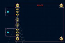
I try to fit all the components on a surface of 95x75 and it is very difficult unless I optimize the type/brand of component as much as possible. I keep hope.
One more question. For C7, can I use this:
https://www.mouser.fr/ProductDetail/KEMET/SMR15105J100B06L165CBULK?qs=lyRJTFulC0YoJ9LrWwxWqg==
Stef.
Ok for question 1 and 3.
For L1, I was asking for a part number for axial or radial coil (not PCB version).
I try to fit all the components on a surface of 95x75 and it is very difficult unless I optimize the type/brand of component as much as possible. I keep hope.
One more question. For C7, can I use this:
https://www.mouser.fr/ProductDetail/KEMET/SMR15105J100B06L165CBULK?qs=lyRJTFulC0YoJ9LrWwxWqg==
Stef.
Attachments
For L1 use a air coil inductor.
For C7 use a polypropylene one MKP or FKP. NOT PPS as you selected.
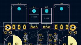
Q13 and Q14 are too close in your PCB. These will dissipate 3.5W each and will get overheated.
Regards,
Tibi
For C7 use a polypropylene one MKP or FKP. NOT PPS as you selected.
Q13 and Q14 are too close in your PCB. These will dissipate 3.5W each and will get overheated.
Regards,
Tibi
Too bad for the PPS. It is compact and efficient.
What would be the minimum distance to be respected between Q13 and Q14?
I don't have too many possibilities in 75mm wide.
Stef.
What would be the minimum distance to be respected between Q13 and Q14?
I don't have too many possibilities in 75mm wide.
Stef.
Hello Stef,
You can use this site to design your own coil.
Single layer air coil calculator
You can use this site to design your own coil.
Single layer air coil calculator
Ok for question 1 and 3.
For L1, I was asking for a part number for axial or radial coil (not PCB version).
Too bad for the PPS. It is compact and efficient.
What would be the minimum distance to be respected between Q13 and Q14?
I don't have too many possibilities in 75mm wide.
Stef.
Distance is relative to heatsink used.
To be on the safe side, mount them as in original QUAD405.
Regards,
Tibi
I would say that having the coil made on a multilayer PCB and mounted vertically on main pcb is the best option. So far Sorin PCB allow this and his coils also measure very well.
Hello Sorin!
If you go through there.
What are the dimensions of your PCB coil?
This is to build a footprint for kicad.
Thanks,
Stef.
Hi,
What is the easiest way to download latest KiCad source files (Q17 and PS) from GitHub. I had some problems with these files.
Br. Jani
What is the easiest way to download latest KiCad source files (Q17 and PS) from GitHub. I had some problems with these files.
Br. Jani
Attachments

Hi,
What is the easiest way to download latest KiCad source files (Q17 and PS) from GitHub. I had some problems with these files.
Br. Jani
The best place to download is from github.
Go to project and click on zipped gerber files for Q17 and/or active power supply.
A new window will open and on the right side you have download button.
Regards,
Tibi
Last edited by a moderator:
Hello everyone,
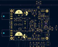
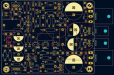
Good news, everything fits in 95x75mm. There is still a lot of work to optimize the parts placements and to trace the tracks of the PCB.
I'm still looking for a part number for a 1.2uH coil. For now, I have made room for a coil of the same size as the one in the original quad405.
Stef.
Good news, everything fits in 95x75mm. There is still a lot of work to optimize the parts placements and to trace the tracks of the PCB.
I'm still looking for a part number for a 1.2uH coil. For now, I have made room for a coil of the same size as the one in the original quad405.
Stef.
Attachments
- Home
- Amplifiers
- Solid State
- Q17 - an audiophile approach to perfect sound