Hallo all,
What is happening with all the other builds, are you guy's happy or any specific problems ?🙂 Tim, I hope you get your build sorted soon !!
I'm still waiting for my boards.
Regards
Jan
What is happening with all the other builds, are you guy's happy or any specific problems ?🙂 Tim, I hope you get your build sorted soon !!
I'm still waiting for my boards.
Regards
Jan
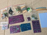
Another full set of boards and some parts, received yesterday from Sorin.
Thank you very much, Sorin !
I'm very grateful for Alex, Mircea and Sorin for sending me these gorgeous boards, unfortunately I'll not have time to test all of them.
Therefore, I would like to pass these boards to others, that may actually build a Q17 based on these and, of course, come back here with feedback and pictures.
To get one of these boards, my condition is that you have already purchased a full set of parts. Send me a mail, at my evotronix mail address, with a picture of all parts and you will get one of these designs at the shipping cost.
FMWPFS - first mail with picture, first served
Regards,
Tibi
Attachments
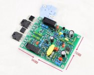
Hello, I ordered such boards, because of the small size and because I need them for less power and I have great difficulties to make the board work in its original form. The problem is that the board behaves like an oscillator.
Only when I replace the coil L1 with one from quad 405, there are oscillations only during start-up and until the voltage of the operational amplifier reaches + - 15v. - then they decrease and after a second they disappear. But this is still unpleasant, because I have to make the speakers relay turn on after 6 seconds. I looked in the forum how to solve this problem, but it does not work for me. In the original circuit with a coil on the board, I have constant generations of about 20 MHz, which do not decrease. Does anyone have any idea how they can help me?
Only when I replace the coil L1 with one from quad 405, there are oscillations only during start-up and until the voltage of the operational amplifier reaches + - 15v. - then they decrease and after a second they disappear. But this is still unpleasant, because I have to make the speakers relay turn on after 6 seconds. I looked in the forum how to solve this problem, but it does not work for me. In the original circuit with a coil on the board, I have constant generations of about 20 MHz, which do not decrease. Does anyone have any idea how they can help me?
Attachments

http208,
One of my observation would be that output is very close to input. Especially the cascode stage is tangent to the L1.
If you want to make a direct replacement for original quad405 board, than go for a small ready available inductor, or make the coil on a separate PCB and mount vertically.
Replacing the coil from original quad405, will imply to change current dumping bridge as well.
This is what you can do.
Cut your pcb coil and use a normal one, but with the right inductance.
For a faster turn-up, you may change R29 and R30 to 1K, or smaller for a shorter transitory time.
Regards,
Tibi
I'm here,if you are looking for a tester😉Another full set of boards and some parts, received yesterday from Sorin.
Thank you very much, Sorin !
I'm very grateful for Alex, Mircea and Sorin for sending me these gorgeous boards, unfortunately I'll not have time to test all of them.
Therefore, I would like to pass these boards to others, that may actually build a Q17 based on these and, of course, come back here with feedback and pictures.
To get one of these boards, my condition is that you have already purchased a full set of parts. Send me a mail, at my evotronix mail address, with a picture of all parts and you will get one of these designs at the shipping cost.
FMWPFS - first mail with picture, first served
Regards,
Tibi
Thimios,
Send me a mail with a picture with all Q17 parts, including trafo and I'll send you a pcb set at shipping cost.
Regards,
Tibi
Send me a mail with a picture with all Q17 parts, including trafo and I'll send you a pcb set at shipping cost.
Regards,
Tibi
Another full set of boards and some parts, received yesterday from Sorin.
Thank you very much, Sorin !
I'm very grateful for Alex, Mircea and Sorin for sending me these gorgeous boards, unfortunately I'll not have time to test all of them.
Therefore, I would like to pass these boards to others, that may actually build a Q17 based on these and, of course, come back here with feedback and pictures.
To get one of these boards, my condition is that you have already purchased a full set of parts. Send me a mail, at my evotronix mail address, with a picture of all parts and you will get one of these designs at the shipping cost.
FMWPFS - first mail with picture, first served
Regards,
Tibi
Thimios,
Send me a mail with a picture with all Q17 parts, including trafo and I'll send you a pcb set at shipping cost.
Regards,
Tibi
Output mosfets , input i.c and 2240 are missing.
Output mosfets , input i.c and 2240 are missing.
I can give you 2SC2240 for free, but when you have all other parts please contact me.
Regards,
Tibi
Hello, I ordered such boards, because of the small size and because I need them for less power and I have great difficulties to make the board work in its original form. The problem is that the board behaves like an oscillator.
Only when I replace the coil L1 with one from quad 405, there are oscillations only during start-up and until the voltage of the operational amplifier reaches + - 15v. - then they decrease and after a second they disappear. But this is still unpleasant, because I have to make the speakers relay turn on after 6 seconds. I looked in the forum how to solve this problem, but it does not work for me. In the original circuit with a coil on the board, I have constant generations of about 20 MHz, which do not decrease. Does anyone have any idea how they can help me?
i assume that you are measuring your wifi. The flat coil is much better to use as a receiver compared to a cylindrical coil.
Hello everyone,
I discovered this project by chance while surfing. Very nice project this Q17. I had a QUAD405 for 20 years. I now have a tweaked clone from LJM that I built a few years ago.
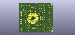
Does a Q17 PCB that fits into a space of approximately 96x76mm exist?
No more space in my box. 😉
Stef.
.
I discovered this project by chance while surfing. Very nice project this Q17. I had a QUAD405 for 20 years. I now have a tweaked clone from LJM that I built a few years ago.
Does a Q17 PCB that fits into a space of approximately 96x76mm exist?
No more space in my box. 😉
Stef.
.
Attachments
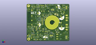
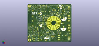
You mean something like this https://twitter.com/tiberiu_vicol/status/1440252543683100675?ref_src=twsrc^tfw
It is a direct replacement for QUAD405 board.
I have a batch of boards, will see when I have time to mount and test one.
Regards,
Tibi
It is a direct replacement for QUAD405 board.
I have a batch of boards, will see when I have time to mount and test one.
Regards,
Tibi
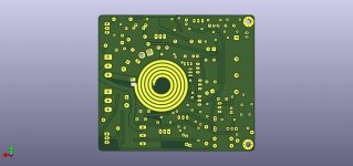
Hello Tibi,
It looks pretty good. I don't have an oven though. 😉
Can you share the gerbers or more 3D views to take a look at in detail?
Cheers,
Stef.
It looks pretty good. I don't have an oven though. 😉
Can you share the gerbers or more 3D views to take a look at in detail?
Cheers,
Stef.
Hello Stef,
I have drawn the small PCB even smaller, so that it is now only 95.1 mm long. I have also made some improvements. You should be able to solder it without an oven.
Regards Tim
I have drawn the small PCB even smaller, so that it is now only 95.1 mm long. I have also made some improvements. You should be able to solder it without an oven.
Regards Tim
Attachments
Last edited:
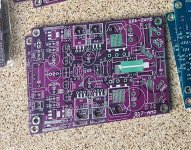
It still goes a little better. 😉 (Yes, this is not as nice as Tibi SMD construction....)
Attachments
Last edited:
Therefore, I would like to pass these boards to others, that may actually build a Q17 based on these and, of course, come back here with feedback and pictures.
Regards,
Tibi
Hi Tiby,
I've read one of the previous post.
What is the size of the violet board?
If it fit in my box, I have the habit to do manually this kind of holes under the PCB. I can test it with a Connex PSU.
Stef.
Attachments
I do not have the board with me now, but that board is made by Sorin and he may give you exact dimension information and BOM.
When you have all the parts, mail me or post here a picture and I'll mail you the boards.
Regards,
Tibi
When you have all the parts, mail me or post here a picture and I'll mail you the boards.
Regards,
Tibi
About power supply.
The best is with trafo, synchronous rectifiers and MLytic caps.
If you go for SMPS, I recommend this one.
It has very low noise, low footprint, not expensive and it was tested by me. It will work just fine with 2 x Q17 with 3 pairs. Go for +/-60V.
Regards,
Tibi
The best is with trafo, synchronous rectifiers and MLytic caps.
If you go for SMPS, I recommend this one.
It has very low noise, low footprint, not expensive and it was tested by me. It will work just fine with 2 x Q17 with 3 pairs. Go for +/-60V.
Regards,
Tibi
Last edited by a moderator:
- Home
- Amplifiers
- Solid State
- Q17 - an audiophile approach to perfect sound