Stef,
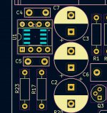
Now I had a closer look on your PCB. Q13 & Q14 do not need a heatsink. Sorry for confusing you. Instead, Q5 & Q6 need to be mounted on a heatsink as they will dissipate ~3,5W each.
Regards,
Tibi
Now I had a closer look on your PCB. Q13 & Q14 do not need a heatsink. Sorry for confusing you. Instead, Q5 & Q6 need to be mounted on a heatsink as they will dissipate ~3,5W each.
Regards,
Tibi
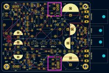
And damn !!
I have to redo everything, or almost.
And no space to add 2 heatsinks. If you have suggestion?
Stef ..
I have to redo everything, or almost.
And no space to add 2 heatsinks. If you have suggestion?
Stef ..
Last edited:
Hi again!
Does this kind of heatsink will be ok for 3.5W?
There are several height versions.
I would have room for this kind of heatsink.
Stef.
FK 240 SA 220 O
https://www.farnell.com/datasheets/17613.pdf
FK 240 SA 220 V
https://www.farnell.com/datasheets/17619.pdf
Does this kind of heatsink will be ok for 3.5W?
There are several height versions.
I would have room for this kind of heatsink.
Stef.
FK 240 SA 220 O
https://www.farnell.com/datasheets/17613.pdf
FK 240 SA 220 V
https://www.farnell.com/datasheets/17619.pdf
Attachments
Last one is the best compromise.
You may move mounting holes inside the board and earn more space between transistors.
Regards,
Tibi
You may move mounting holes inside the board and earn more space between transistors.
Regards,
Tibi
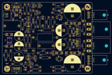
Your board need to end where the mounting holes are ?
I will extend the board on the right, a bit, to get some extra space between top and low transistors.
Power resistors are OK and will not run hot.
Regards,
Tibi
I will extend the board on the right, a bit, to get some extra space between top and low transistors.
Power resistors are OK and will not run hot.
Regards,
Tibi
This is how I will do. 🙂
Regards,
Tibi
Wil do it.
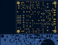
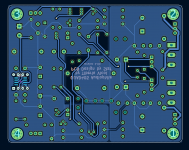
I have less than 10 hours on KiCAD. I don't really understand how it works for grounding (GND and GNDPWR).
To do as you with the two larges flats blues zones.
Have a good evening.
Stef...
Attachments
Hallo Alex,
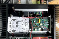
How is your build doing ? Put up some snappies please. Are you happy with the sound ? Hope you did not caught the evil covid in between !!🙂
The others guy's builds as well, plse give some feedback !
How is your build doing ? Put up some snappies please. Are you happy with the sound ? Hope you did not caught the evil covid in between !!🙂
The others guy's builds as well, plse give some feedback !
Wil do it.
I have less than 10 hours on KiCAD. I don't really understand how it works for grounding (GND and GNDPWR).
To do as you with the two larges flats blues zones.
Have a good evening.
Stef...
Stef,
Use filled zones (ALT + Z), than double click-it and assign to the zone the net you want (GND, GNDPWR etc.)
Regards,
Tibi
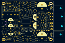
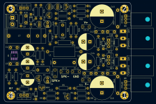
Thanks Tibi.
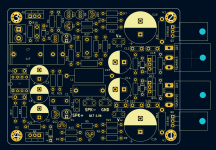
I figured out how to do it.
The PCB is finished. I must now check it quietly.
Stef.
I figured out how to do it.
The PCB is finished. I must now check it quietly.
Stef.
Attachments

Last edited:
ATTENTION
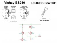
Several people reported to me that BS250 are reversed on my PCB.
Depending on which mosfet manufacturer you have purchased this is true and also not true.
I use in my design Vishay in TO-92.
As per datasheet https://www.vishay.com/docs/70209/70209.pdf source is on pin numbered 3.
In same datasheet are mentioned TP0610L VP0610L who have source at pin 1.
If you make use of BS250 from Diodes https://www.diodes.com/assets/Datasheets/BS250P.pdf
this have source also at pin 1.
So take care which BS250 are you using and mount correctly, otherwise your amplifier will make a big fisss, or boom, or plici ...
Regards,
Tibi
Seems Vishay is no longer available. I'll change pcb layout for Diodes one and mark GDS on pcb as well.
Regards,
Tibi
Regards,
Tibi
Seems Vishay is no longer available. I'll change pcb layout for Diodes one and mark GDS on pcb as well.
Regards,
Tibi
Yes please Tibi, change the gerbers as most of us have got the Diodes Inc. one for BS250P. I have this one - https://in.element14.com/diodes-inc/bs250p/mosfet-p-ch-45v-0-23a-150deg-c/dp/3405170
But not yet printed any PCB boards and will wait for your new gerbers.
Thanks

- Home
- Amplifiers
- Solid State
- Q17 - an audiophile approach to perfect sound