Hello,
I have another idea for the problem that there is always some component that is not available. Therefore, I have added the SMD solder pads for the SMD version of the small transistors to the PCB. I assume that these are equivalent to the large ones. The power dissipation of the SMD transistors is given as 300mW, which is surely sufficient, isn't it Tibi?
Regards Tim
Yes, it is.
Regards,
Tibi
Stef,
Thank you for your observation and your fork. Q2 is pnp and a replacement for 2SA970 is KSA922. I'll update too.
Regards,
Tibi
Thank you for your observation and your fork. Q2 is pnp and a replacement for 2SA970 is KSA922. I'll update too.
Regards,
Tibi
...
We can read this but Q12 is a plastic TO-92!!
Stef.
Code:Q12 must be mounted on heatsink too, as it will be used to compensate final stage thermal run away.
It is plastic, but still has some thermal conductivity and will work just fine. Use thermal grease or thermal glue, for better heat transfer.
Regards,
Tibi
Hi Tibi!
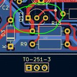
For Q12, couldn't we find a slightly bigger MOSFET, like a TO-251-3 package ?
Cheers,
Stef.
Through Hole TO-251-3 N-Channel MOSFET – Mouser France
For Q12, couldn't we find a slightly bigger MOSFET, like a TO-251-3 package ?
Cheers,
Stef.
Through Hole TO-251-3 N-Channel MOSFET – Mouser France
I prefer Q12 as bipolar, because is part of a ccs and his Vbe/R13 is used as reference for class A current stage.
Mosfet have large variations in Vgs and this will complicate current adjustment.
Regards,
Tibi
Mosfet have large variations in Vgs and this will complicate current adjustment.
Regards,
Tibi
Last edited by a moderator:
Sorry error not MOSFET but BJT.
As the 2SC4135S ?
https://www.mouser.fr/ProductDetail/onsemi/2SC4135S-E?qs=5C9Q4QJFsuOd4kQO02IP6g==
Stef.
EDIT: We post at the same time.
As the 2SC4135S ?
https://www.mouser.fr/ProductDetail/onsemi/2SC4135S-E?qs=5C9Q4QJFsuOd4kQO02IP6g==
Stef.
EDIT: We post at the same time.
Attachments
Last edited:
Power dissipated over Q12 is very low ~20mW. You may use BD139. It is overkill, but easier to mount on heatsink. Select one with higher beta.
Maybe BD135 have higher beta !?
Regards,
Tibi
Maybe BD135 have higher beta !?
Regards,
Tibi
Last edited by a moderator:
The notion of "ß" is obscure for me. Sorry.
What Is BJT Beta? Understanding the Current Gain of a Bipolar Junction Transistor - Technical Articles
Heatsink for TO-126
https://www.mouser.fr/datasheet/2/303/sink_c-1265560.pdf
But the cheapest is this kind of little heatsink.
The TO-251 is great too as it include a large metal part. No need of heatsink.
The downside is that it is an old type of package. Less reference available.
Stef.
Attachments
Last edited:
Hello Stef,
Q12 should be in contact with the heat sink of the power transistors, as this is a thermometer in a broader sense and depending on the temperature of the radiator works differently.
For your layout in the compact enclosure, you should simply ignore this. In the case of the Q17, it is also more interesting for electronics engineers and perfectionists than practically useful, as the cooler of the Q17 is usually at room temperature.
Hi Folks!
I ordered the components for the Q17 project. Finally, I had to place an order from Farnell, a second from Mouser, a third from RS and a fourth from eBay. It becomes complicated to tinker with this shortage of components.
I am waiting to have the components to order a batch of PCB. I would like to do a final "physical" check of the PCB with the components in hand.
Good day,
Stef.
Attachments
Hello Stef,
Q12 should be in contact with the heat sink of the power transistors, as this is a thermometer in a broader sense and depending on the temperature of the radiator works differently.
For your layout in the compact enclosure, you should simply ignore this. In the case of the Q17, it is also more interesting for electronics engineers and perfectionists than practically useful, as the cooler of the Q17 is usually at room temperature.
Thanks Tim for the details.
I've moved Q2 to the border in case of. 🙂
Stéphane
Attachments
Hi Folks!
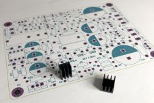
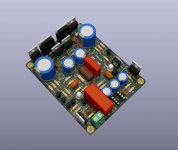
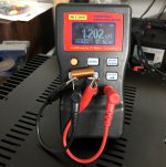
It works! As the online calculator. 😉
The PCB is almost ready. Just waiting for one component to check the size.
I plan to order five PCBs to jlcpcb.
Stef.
.
It works! As the online calculator. 😉
The PCB is almost ready. Just waiting for one component to check the size.
I plan to order five PCBs to jlcpcb.
Stef.
.
Attachments

Last edited:
Yes, 1mm wire with an interior diameter of 8mm.
Be careful, sometime they sale 1mm wire but in fact, they are 1.18mm. This one is a real 1mm (1.05).
Stef.
Be careful, sometime they sale 1mm wire but in fact, they are 1.18mm. This one is a real 1mm (1.05).
Stef.
Last edited:
Hello!
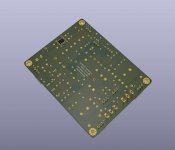
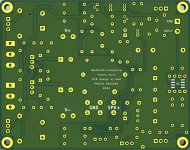
I published on my Github repository, the version 1.0 of the Q17-Mini board including the Gerber files (Gerber-Q7-Mini.zip).
GitHub - stefaweb/Q17-a-QUAD405-audiophile-approach: Q17 is an error correction amplifier based on the QUAD405 current dumping principle
I should order the PCBs tomorrow morning. You have all night to find errors.
Cheers,
Stef.
.
Attachments

Congratulations on your great work, I recently finished building a replica of the original. if I found this post much earlier I would surely have mounted this one.
Best regards!
Best regards!
neofox33,
tivicol is the designer of the circuit and KMDAudio is the designer of this board layout, I'm only a builder that got the Gerber files from KMDAudio.😉
tivicol is the designer of the circuit and KMDAudio is the designer of this board layout, I'm only a builder that got the Gerber files from KMDAudio.😉
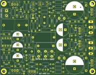
Github files have been updated.
Have corrected an issue at output connector, for second time. 🙁
All traces have been rounded.
Q5 and Q6 are mounted at the edge of the board, with castellated holes, making easier to solder and mount.
Power supply pcb was slightly updated, mostly aesthetic.
Regards,
Tibi
Have corrected an issue at output connector, for second time. 🙁
All traces have been rounded.
Q5 and Q6 are mounted at the edge of the board, with castellated holes, making easier to solder and mount.
Power supply pcb was slightly updated, mostly aesthetic.
Regards,
Tibi
- Home
- Amplifiers
- Solid State
- Q17 - an audiophile approach to perfect sound