Well my boards are ordered, special thanks to Mircea from KDMaudio for the files.
Much appreciated !
Cheers Jan, good to hear ! What was your color of choice ? 😀
Mircea, it will be black and white,
Now busy with sorting out the BOM, did anybody perhaps put a BOM together ?🙂 Im working through that mail of Tibi.
You will be finished before me, let's hope its a winner.😀
Now busy with sorting out the BOM, did anybody perhaps put a BOM together ?🙂 Im working through that mail of Tibi.
You will be finished before me, let's hope its a winner.😀
Can this amplifier in the bridge connection work at a load of 8 ohms? The supply voltage is +-50 volts. Do I need to add a second pair of output transistors?
Yes, will work with a single pair of FQA's very well.
However, depending on your speakers you may need to add one more pair or more.
Regards,
Tibi
However, depending on your speakers you may need to add one more pair or more.
Regards,
Tibi
Tibi,
Would it be acceptable to mount an output coil with 10R resistor in parallel on the output of the amps ?
Would it be acceptable to mount an output coil with 10R resistor in parallel on the output of the amps ?
I'm not a big fan of amplifier output coil.
As an audiophile, I would say that using better quality speaker cables will bring far better "improvement" than output coil.
Also I consider that matching Zobel network with your speaker, will also add considerable improvement.
Regards,
Tibi
As an audiophile, I would say that using better quality speaker cables will bring far better "improvement" than output coil.
Also I consider that matching Zobel network with your speaker, will also add considerable improvement.
Regards,
Tibi
Hello
my board with three pairs of outputs does not play cleanly, I have not been able to fix the defect so far, I have no idea what it is.
The amp starts playing very clean and after one song, sometimes earlier it starts with something like distortions - it's not typical, more like a kind of echo, like it would oscillate.
As OP I have the OPA 1656, OPA 1612 and OPA 1642, which basically behave similarly.
So far I can't see any advantage in the variant with three output pairs. In contrast, the simple one plays very well and can also handle very large speakers in an exemplary manner.
A question for everyone:
Has anyone already tested a Q17 with three pairs of outputs? How does it play in practice?
Has anyone already tested a Q17 with three pairs of outputs? How does it play in practice?
Q17 was tested OK with 4 pairs.
I think you have a thermal issue, most probably with class A driver stage. Use a thermal camera and see what's going on.
Make sure transistors have properly contact with heatsink.
Regards,
Tibi
I think you have a thermal issue, most probably with class A driver stage. Use a thermal camera and see what's going on.
Make sure transistors have properly contact with heatsink.
Regards,
Tibi
Hello Tibi,
It's not the cooling.
I have now tested everything possible and replaced components, so I have to assume that it is a layout error and that the use of a dual OP was a mistake with this variant.
Regards Tim
It's not the cooling.
I have now tested everything possible and replaced components, so I have to assume that it is a layout error and that the use of a dual OP was a mistake with this variant.
Regards Tim
Maybe the OPA get hot ?
Second half of the OPA must have both inputs connected to ground.
Regards,
Tibi
Second half of the OPA must have both inputs connected to ground.
Regards,
Tibi
A question for everyone:
Has anyone already tested a Q17 with three pairs of outputs? How does it play in practice?
Without really knowing i would expect it behaves like any other amp.
A single pair should offer the best midrange and highs. The more pairs one adds, the more solid the bass becomes but always at the expense of midrange clarity.
As with everything else it is a questions of which compromise works better. Difficult speakers demand more than a single pair even at low volumes.
Separate amps for the bass drivers is one possible solution.
Maybe the OPA get hot ?
Second half of the OPA must have both inputs connected to ground.
Regards,
Tibi
Hello Tibi,
I used the second channel of the OP as an input amplifier or as an inverter for the bridged channel. This gives me a total gain in the OP of 14 (7 for the amplifier, 2 for the input amplifier).
It doesn't matter now, I have disassembled the amplifier, and desoldered the Q17 boards.
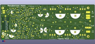
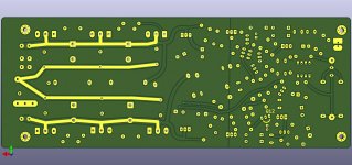
I'm giving the 3 output stage Q17 another chance and have drawn a new layout for it. Again included are footprints for large foils. It doesn't seem ideal what the Wima MKP2 can do, the FKP capacitors sound better. I want to experiment further with C7. My setup with 33nF FKP2 + 1000nF MKP2 played, but just the MKP2 alone was not enough, that was one of the findings from today. Therefore, the old layout was not optimal at this point.
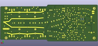
During the revision, I now also moved the coil to the end, so I spare a useless conductor track and I can place the coil further away from the transformer. A very low humming noise was also a deficiency of the construction.
I have also further optimised the tracks and prepared the bottom side of the board for the additional tinning of the tracks.
I'll see what other optimisation options I can come up with in the next few days. For now, this is a board that can show the characteristics of the very well playing two output stage boards.
Regards Tim
Attachments
I don't have any 2cs2240/2sa970, can I use something else?
Thanks
hi,
in the manual, the types are: 2SA992 and 2SC1845, or the new names KSA992 and KSC1845.
Tell me, please. Do I understand correctly that this amplifier works in Class A up to a certain low power? Are the output transistors closed at this moment? At what output power of the amplifier do they start working?
Amplifier output stage is working in class B, but his operation is far more complex than a standard A/B amplifier. I suggest you to read original QUAD405 PJ Walker and Vanderkooy-Lipshitz documents for deeper understanding.
Regards,
Tibi
Regards,
Tibi
Hello,
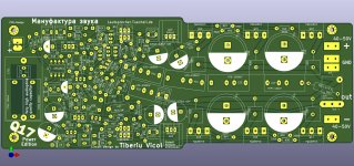
I have continued to develop my PCB design, keeping all the essential features of the setup with one or two pairs of output transistors. This is built on a board like the experimental board ( #218 and #253) and has been playing very very well for many hours.
The main difference is the 3rd pair of output transistors and the transistors turned outwards, as well as the footprints for cup electrolytic capacitors. In this case, the transistors to be cooled can be attached to a 50 mm wide aluminium rectangular tube (which is why the driver transistor footprints were doubled), as well as to a wide radiator of at least 114 mm width.
Instead of the potentiometer to regulate R24+R25 I now added a parallel resistor which remains empty depending on the input voltage. R23 is again represented with 10k and can be reduced in value by an additional parallel resistor (this also leads to interference at some point, I had determined 8kOhm in a test setup with two pairs of output transistors and used 8.2k in the finished setup).
For C7 there is a large field of slots for a large number of possible types, also the parallel connection as I implemented it in the experimental board is available.
The capacitors for ripple minimisation and for increasing the small signal power due to the high current capability of foils can be populated in a wide grid of P5/P10/P15/P22.5, depending on how big and in which quality you want to make them. This is even more convenient than with the experimental board.
I made space for Styroflex capacitors C1 and C10 so that you are not limited to Wima or other small foils.
At Mouser, the OPA1641 is not available in the large design (SOIC), so I immediately wrote the OPA1611 onto the layout. I have tested it successfully.
During my experiments with the latest amplifier, I could detect subtle differences in the sound of the OPA1612, OPA1642 and OPA1656, despite all the feedback it generated. The OPA1612 sounded very precise and distinctly realistic. The OPA1656, on the other hand, sounded nicer, not as accurate in its acoustic representation. The OPA1642 sounded a little more striking with an emphasis on the voice. However, the differences are very small. In contrast, an OPA2134 plays harsh and pale in the bass. Compared to these standard types, the three OPAs mentioned above have a clear gap in naturalness, fine resolution, bass precision and resolution in the high frequencies. For me personally, this test confirms that the OPA1611 is very well suited for the Q17 amplifier.
I have now ordered the boards, so I expect to be able to report back by the end of the month whether a version with three pairs of output transistors can then offer any advantages on hi-fi speakers, compared to the standard version from Tibi.
Regards Tim
Attachments
- Home
- Amplifiers
- Solid State
- Q17 - an audiophile approach to perfect sound