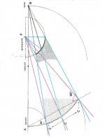
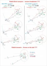
Fact is, because of the geometry of the arm an inherent skating force must be present, and you are not ready to prove or disprove this fact with a very clear and simple method.
Okay, briefly. Busy day today. I've been watching the drama here.
First the good stuff: Jim - you've produced an attractive arm using novel methods and it apparently moves freely and tracks accurately. You recognized the need for vertical adjustment and added it. Those aren't small accomplishments.
Now for the argy bargy: The term "skating" isn't being used correctly. Skating is a specific tonearm behavior that results from specific condition: Headshell offset. Saying an arm is reacting to gravity and swinging around its pivot and that's skating is like saying a swinging pendulum is skating.
Wife's calling. More later.
You balanced and zeroed out the vertical arm to put it in neutral position that results in zero vertical tracking force (VTF) but you haven't proven the horizontal arm is perfectly balanced because there's no adjustment for it. How do we know the leveling of the base is not compensating any horizontal imbalance or inherent friction? The horizontal arm is held in place by two vertical spikes that creates a vertical straight line and what if this verticality is skewed slightly and then the base is adjusted to compensate this imbalance?
I don't see why Frank's arm cannot use slight offset to counter the skating force or stylus drag, etc.., you just have to tweak it ever so slightly until it's neutral. Your outward skating video has probably too much counterforce.
At this point, it probably doesn't even matter since it's so slight that, as I said, that the Birch style arm is a viable option for tangential tracking that generate very little skating force and allows various designs in the geometries, bearings, mounting systems, guiding mechanisms, segment lengths, materials, etc... I wish there will be more diy projects AND commercial products to allow users to choose from.
Ok. Here is another video to show the arm is balanced horizontally. When you watch this video, you need always reference to the video titled, no skating 3, I posted in the post #120 because I simply added extra counter weight on the arm without touching anything else. Once I add extra counter weight, I can see how the arm behaviors in horizontal plane.
no skating 3 - YouTube
In the video, no skating 3, you can clearly see the arm doesn't skate.
no skating perfectly leveled 3 - YouTube
First, I did add adjustment on the base once I realized the importance of level adjustments. I use three set screws. In video above titled, no skating perfectly leveled, the arm is balanced horizontally since the arm is stationary. It doesn't move by itself. If the arm is not balanced horizontally, it will move to side by itself. In other words, the base is perfectly leveled. Therefore, the arm doesn't skate. Once the arm skates, the base MUST be leveled INCORRECTLY. Non-skating and leveled are always in pair. So is skating and mis-leveled.
One thing you may see from the video is my arm has a tendency to move back to original position in both inward and outward once I stuck the arm slightly.
Last edited:
Let's take a hypothetical perfect PLT, frictionless bearings, absolute alignment in both axes, the arm vertically neutral then attach Ray's string and pull. The arm will swing forward and toward the pivot. I am convinced it will show "skating," and fail the test, but there are at least two questions. Carlo has asked: How do you apply the exact equivalent of stylus drag and does it make a difference? And my question is and has been: How much of that movement is simply the geometry doing exactly what it's supposed to do and how do you separate those forces and results? If you pull at the headshell, the PLT will move forward and inward. If you push sideways at the outer pivot, the headshell will move forward and inward. If you push the CW from the rear, the headshell will move forward and inward. Same dance everytime.
In other words "how much and why?" Carlo and I have both tried to answer the second question. Building a test rig which might answer the first question wouldn't be difficult, but, since the forces are so small, actual measurement could be tricky.
Jim hypothesized that PLTs inherently have no skate, built his arm to prove that, and believes he was successful. My take is that he has built a (potentially) excellent arm, but I believe his tests so far don't confirm his no skate hypothesis, but do show how small the existing forces are. I still consider skating in PLTs to be a hobgoblin since the forces are so small and easily dealt with as to be almost irrelevant.
I suggest the reason for designing and building a PLT is because, if successful and correctly set up, it will do a nearly perfect job of putting the stylus precisely where it should be at any point and moment on the record and, consequently, allow the cartridge to reproduce what's recorded accurately and to send the best possible signal to the rest of our system and to us.
The real test of Jim's arm will be how well it does that. I think it just might pass.
Attachments
Last edited:
Doug,
I don't dispute the skating of a PLT arm conceptually. I merely state a fact that my 6B, which is a PLT arm, doesn't skate. Is this a special case? Does the arm embed an anti-skate force from its structure? Or, is the skating force too small? I don't know. I just can't say the arm skates while it doesn't.
I will be happy to see someone can find the flaws in my test but I don't see anyone did so far. The result is not what I expected.
Jim
Last edited:
A more accurate method to determine if an arm is level would be 2x (in-out) starting torque test with a pendulum.
With the nature of PTT arms even a 4x (i-o-f-b) might reveal something. I'll try on Friday.
Visually observing the effect about 0.0009Nm of force has on multiple linkages will always be a challenge.
It might not be surprising if the SF is damped out by the inefficiencies in the linkages, and the result should probably be observed in the cart compliance and not in the arm movement.
Nice work Jim, keep going, there is more to learn here.
The tonearm has turned out nice. How does it sound ?
some newbie random thoughts.
Level :
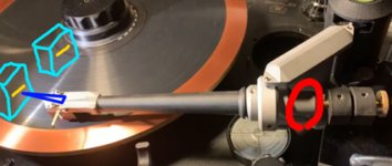
as we dont know all the multiple bearings are on same axis (perfectly Parallel to each other) the bubble level at base would give mixed results. we only want the horizontal tonearm movement to be (already leveled ) platter.
Please look at picture. If one clamps down the vertical movement of tonearm (Shown in red circle), fix a sharp pointer (Blue) on headshell with tape, Have a perfectly flat square piece (Amy material/shown in cyan color) with marking. and if tonearm base has level alignment screws. Just adjust so that pointer on headshell meets marked level on the piece. Move the piece to record lable . Move the tonearm and adjust the tonearm level.
String test :
String test though I like it very much will have different effect in such arm as any pull will move the whole bearing assembly towards the pull and our judgement can be wrong.
Skating force :
Very difficult to understand (for me) and evaluate. But if we think logically the multiple bearing friction will override whatever small skating force is there. Also the stylus drag would also be greater if we presume that the drag is pulling the whole tonearm in the geometry (the four bearings near the tonearm end) that we want, along with groove friction.
If one has blank record or Laser disc would that be of any help in understanding skating for this particular arm ? Or some test records ?
here are some videos.
Everything You Know About Skating Is Wrong! | Analog Planet
As nothing is perfect in the world overall from videos my primitive mind thinks this is a good DIY and good tonearm from linear tracking point of view..
Thanks for the effort and excellent work 🙂
Regards
some newbie random thoughts.
Level :
as we dont know all the multiple bearings are on same axis (perfectly Parallel to each other) the bubble level at base would give mixed results. we only want the horizontal tonearm movement to be (already leveled ) platter.
Please look at picture. If one clamps down the vertical movement of tonearm (Shown in red circle), fix a sharp pointer (Blue) on headshell with tape, Have a perfectly flat square piece (Amy material/shown in cyan color) with marking. and if tonearm base has level alignment screws. Just adjust so that pointer on headshell meets marked level on the piece. Move the piece to record lable . Move the tonearm and adjust the tonearm level.
String test :
String test though I like it very much will have different effect in such arm as any pull will move the whole bearing assembly towards the pull and our judgement can be wrong.
Skating force :
Very difficult to understand (for me) and evaluate. But if we think logically the multiple bearing friction will override whatever small skating force is there. Also the stylus drag would also be greater if we presume that the drag is pulling the whole tonearm in the geometry (the four bearings near the tonearm end) that we want, along with groove friction.
If one has blank record or Laser disc would that be of any help in understanding skating for this particular arm ? Or some test records ?
here are some videos.
Everything You Know About Skating Is Wrong! | Analog Planet
As nothing is perfect in the world overall from videos my primitive mind thinks this is a good DIY and good tonearm from linear tracking point of view..
Thanks for the effort and excellent work 🙂
Regards
Attachments
the result should probably be observed in the cart compliance and not in the arm movement.
Bingo!
A high compliance cartridge with long cantilever will be easier to tell the result or cantilever deflection visually.
Last edited:
2wice,
It is a good idea.
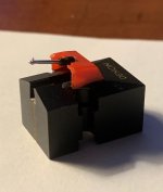
The dummy cartridge I am using for tests is a Crosley stylus glued on the case of Denon 103. I also added some weight in the case to make the testing cartridge about 10 grams. I am going to make a new dummy cartridge. Please see the photo. The cantilever is well exposed so it is easy for me to see the deflection of the cantilever. I don't know the compliance of Crosley stylus, but it seems high to me by touching the stylus.
Such test may only prove how efficient the linkage is. Next conclusion maybe is still a speculation. If the linkage is inefficient, the linkage may cancel the skating force out. If the linkage is efficient, there is still the possibility that the skating force is cancelled out or something else which I don't know.
In any cases, it is a good idea to see how efficient the linkage is to know more about my 6B.
Jim
It is a good idea.
The dummy cartridge I am using for tests is a Crosley stylus glued on the case of Denon 103. I also added some weight in the case to make the testing cartridge about 10 grams. I am going to make a new dummy cartridge. Please see the photo. The cantilever is well exposed so it is easy for me to see the deflection of the cantilever. I don't know the compliance of Crosley stylus, but it seems high to me by touching the stylus.
Such test may only prove how efficient the linkage is. Next conclusion maybe is still a speculation. If the linkage is inefficient, the linkage may cancel the skating force out. If the linkage is efficient, there is still the possibility that the skating force is cancelled out or something else which I don't know.
In any cases, it is a good idea to see how efficient the linkage is to know more about my 6B.
Jim
Attachments
Last edited:
Hiten,
The arm is not wired yet. This will be my next step. I am going to do another test so I can know how efficient the linkage is.
Jim
The arm is not wired yet. This will be my next step. I am going to do another test so I can know how efficient the linkage is.
Jim
laser disk as blank record
Laser disk! I never thought of using laser disk as a blank test record. That's a brilliant idea. Because of its mirror surface, it's even more effective in detecting skating or side forces. I need to dig out my Criterion collection! 😀
There are some juicy and feisty comments in the comments section! A few of them even touched on the topic of pivoting tangential tonearms. Worth reading.
The article also suggests using a stylus with a spherical tip to eliminate variables.
If one has blank record or Laser disc would that be of any help in understanding skating for this particular arm ? Or some test records ?
Laser disk! I never thought of using laser disk as a blank test record. That's a brilliant idea. Because of its mirror surface, it's even more effective in detecting skating or side forces. I need to dig out my Criterion collection! 😀
here are some videos.
Everything You Know About Skating Is Wrong! | Analog Planet
There are some juicy and feisty comments in the comments section! A few of them even touched on the topic of pivoting tangential tonearms. Worth reading.
The article also suggests using a stylus with a spherical tip to eliminate variables.
small enough
That's my conclusion too that the skating force is small enough not to agonize over and these Birch style arms provide a real option in tangential tracking alongside with parallel trackers a la air-bearing, mechanical/roller, and servo. I also prefer this over the Garrard Zero/Thales/RS Labs swiveling headshell arms and the Klaudio Rube Goldberg arm.
My take is that he has built a (potentially) excellent arm, but I believe his tests so far don't confirm his no skate hypothesis, but do show how small the existing forces are. I still consider skating in PLTs to be a hobgoblin since the forces are so small and easily dealt with as to be almost irrelevant.
That's my conclusion too that the skating force is small enough not to agonize over and these Birch style arms provide a real option in tangential tracking alongside with parallel trackers a la air-bearing, mechanical/roller, and servo. I also prefer this over the Garrard Zero/Thales/RS Labs swiveling headshell arms and the Klaudio Rube Goldberg arm.
I did similar tests way before them. I uploaded the videos on Youtube in 2017. The videos were made even early. The only difference was I reduced effective length and they moved the mount position. You may see all the videos on my Youtube channel.
I used a nice Lyra mc cartridge for testing. The cartridge was completely destroyed after the tests. It was re-tipped by Sound Smith later on.
I used a nice Lyra mc cartridge for testing. The cartridge was completely destroyed after the tests. It was re-tipped by Sound Smith later on.
Last edited:
Although I think the surface makes no difference, I still gave it a try. Here is a video to show the arm was ridding on a piece of plastic. Its surface is almost as smooth as a Laser video disk. There is no difference.
no skating 4 - YouTube
The image is to show the surface of the plastic.
no skating 4 - YouTube
The image is to show the surface of the plastic.
Attachments

Oops
Apologies! The earlier post I misistakenly credited the below quote to Hiten when it should be dtut. Oops!
Apologies! The earlier post I misistakenly credited the below quote to Hiten when it should be dtut. Oops!
My take is that he has built a (potentially) excellent arm, but I believe his tests so far don't confirm his no skate hypothesis, but do show how small the existing forces are. I still consider skating in PLTs to be a hobgoblin since the forces are so small and easily dealt with as to be almost irrelevant.
As a commercial product the Schröder LT does have leveling adjustment as explained by Frank from another thread, quoted below. As you can see in this picture that the base is a 3 point design for micro-leveling with one mounting bolt and two adjustable set screws.
I studied Schröder LT again. LT has one fixed mount screw in the back and two adjustable set screws in the front. It is clear that Frank thinks the adjustments need to be left and right side only, not front and back. In my opinion, the adjustments should be all way around. On my 6B, I added three set screws. The level can be adjusted 360 degrees. I am also trying to modify 6C to have an easy adjustment mechanism. Frank, if you are reading this thread, please correct me if I miss anything.
Last edited:
I just did the test for the bearings.
The record is an old mono LP. I expended the center hole about 2 mm to create an artificial eccentricity. The 2 mm eccentricity should be considered as high level in reality. The VTF was set at 1.76-1.79 grams. I don't know what is the correct VTF for the stylus. It seems to me that 1.79 is a bit heavy for the stylus since its case was lower than normal for a mc cartridge. Here is the video.
bearing test - YouTube
From the video, I would say the bearings are not bad at all. I would guess that the bearings are good enough for not cancelling skating force unless the skating force is really small.
Last edited:
I studied Schröder LT again. LT has one fixed mount screw in the back and two adjustable set screws in the front. It is clear that Frank thinks the adjustments need to be left and right side only, not front and back. In my opinion, the adjustments should be all way around.
Three points make a plane. If you have a fixed point at the bolt position and adjust the height of other two points of set screws you can achieve a level plane, including the option of tilt to two directions. If the two set screws are both adjusted higher than the bolt, you get front and back adjustment. It's simple and elegant.
- Home
- Source & Line
- Analogue Source
- Building a Tuthill/Reed 5A Tangential Tracking Pivot Tonearm