The purpose to build a clone of Reed 5A is to approve that a tangential tracking pivot arm based on Birch geometry won’t skate.
You stated that your goal is to prove that a Birch tonearm does not skate, but you reject every method to measure or to test skating. Nobody knows the friction of your bearings, so the test with the blank disk is not conclusive.
The string test is not flawed, why would is be flawed?
I can not test anything because I do not have (and will not have) a Birch tonearm. Too many bearings.
I'm out from now on.
The initial purpose was to build a clone of Reed 5A to test if it skates or not. But later on, I found a geometry which is slightly simpler than Reed 5A. I am reluctant to copy someone's arm. I also realized that if I want seriously investigate the skating force, I need to build an arm at its full capacity.
I only reject your methods. In my opinion, they don't make sense to me at all. In my stylus stress test video, it shows how efficient the bearings are. From the video, I can conclude that the bearings are very efficient.
I only reject your methods. In my opinion, they don't make sense to me at all. In my stylus stress test video, it shows how efficient the bearings are. From the video, I can conclude that the bearings are very efficient.
Last edited:
Alighiszem,
Before you go, would you post a picture of the geometry you based your calculations on? I'm very interested in how you did that because I've never understood how to separate all the forces involved.
And I agree with you that the simulation 2wice generously offered would be very valuable for all of us.
Last edited:
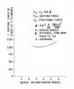
I don't know what formula alighiszem used but I know Kogen's. See attachment. However, Kogen's formula is for regular pivot arms. Does it need some modifications for PT arm? I don't know since I am not good at math. At least, there is a problem that which pivot is for effective length.
The purpose I used a larger Thales circle was to reduce tracking errors. If his calculation is correct, it reduces skating, too.
The purpose I used a larger Thales circle was to reduce tracking errors. If his calculation is correct, it reduces skating, too.
Attachments
Last edited:
Gentlemen,
I dont have means or knowledge to practically make an arm so pardon for posting.
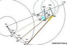
Over the years I have collected lots of article about turntable and tonearms just to learn. I reread the kogen article (Audio magazine October 1967) Since we do have unavoidable offset + Groove friction there is skating force but the same force is acting on one of the pivot which has some mass and resistance which keeps the stylus tangent (See cyan arrow in the pic) to the groove and moving headshell up as the angle (Shown in yellow ) need to be constant. Now since bearing has friction and mass the skating force though may be present is dynamically (On instant) is becoming nil or negligible. This is what I understand with my limited brain.
So we will not have a clearcut answer that tonearm has ZERO skating force because it is changing on the fly along with the movement to almost zero. Now for such a small skating force with lots of variable and dynamic changes (Platter tonearm level,. Stylus shape, groove Modulations, bearing friction, Stylus force etc.) Probably only way is test record.
If anyone is interested the same kogen article has a simple one bearing device (To be Mounted on the headshell) to see skating force. Will be very easy to make.
sorry again as I dont speak with confidence as I have limited knowledge. 😱
Regards
I dont have means or knowledge to practically make an arm so pardon for posting.
Over the years I have collected lots of article about turntable and tonearms just to learn. I reread the kogen article (Audio magazine October 1967) Since we do have unavoidable offset + Groove friction there is skating force but the same force is acting on one of the pivot which has some mass and resistance which keeps the stylus tangent (See cyan arrow in the pic) to the groove and moving headshell up as the angle (Shown in yellow ) need to be constant. Now since bearing has friction and mass the skating force though may be present is dynamically (On instant) is becoming nil or negligible. This is what I understand with my limited brain.
So we will not have a clearcut answer that tonearm has ZERO skating force because it is changing on the fly along with the movement to almost zero. Now for such a small skating force with lots of variable and dynamic changes (Platter tonearm level,. Stylus shape, groove Modulations, bearing friction, Stylus force etc.) Probably only way is test record.
If anyone is interested the same kogen article has a simple one bearing device (To be Mounted on the headshell) to see skating force. Will be very easy to make.
sorry again as I dont speak with confidence as I have limited knowledge. 😱
Regards
Attachments
I don't know what formula alighiszem used but I know Kogen's.
I stated in #11 what I use. It is equivalent whit Kogen's.
Your answer was "This is exactly what I think. The model does match my skating diagram perfectly."
Alighiszem,
Before you go, would you post a picture of the geometry you based your calculations on? I'm very interested in how you did that because I've never understood how to separate all the forces involved.
And I agree with you that the simulation 2wice generously offered would be very valuable for all of us.
I try to, although I am not good at drawing.
Any chance you can list the parts and their mass, please, Jim?
I'd like to factor in inertia, this might allow the determination of what magnitude of motion friction would be required to damp out SF.
I'd like to factor in inertia, this might allow the determination of what magnitude of motion friction would be required to damp out SF.
Any chance you can list the parts and their mass, please, Jim?
I'd like to factor in inertia, this might allow the determination of what magnitude of motion friction would be required to damp out SF.
I modeled the same arm in Fusion 360, too. The arm is slightly different from the version I did in Sketchup. Please see attached image. Thank you for your time!
Attachments
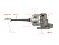
Thank you very much, I'll build the simulation, but I can tell off the bat having over 1/3 of a kilogram in the motion parts of the tonearm might be a concern.
I thought about this when I was modeling the arm. The weight of the arm can be reduced. However, I have a tendency to make everything heavy duty.
There is another possibility that the heavy moving parts is one of the reasons to cancel small skating force.
There is another possibility that the heavy moving parts is one of the reasons to cancel small skating force.
Last edited:
There is another possibility that the heavy moving parts is one of the reasons to cancel small skating force.
Top of the list ATM.
I stated in #11 what I use. It is equivalent whit Kogen's.
Your answer was "This is exactly what I think. The model does match my skating diagram perfectly."
Your calculation is problematic. My thinking like everybody else is a process. Certain sentences may not represent my view completely. Your previous drawing was wrong conceptually.
Here are the 4 reasons that I think your calculation is problematic.
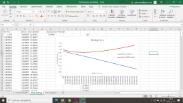
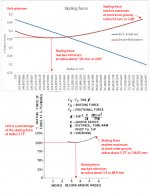
1, Please see the image. The main conflict between your calculation and Kogen’s calculation is when the skating force reaches its maximum level. For a regular pivot arm, yours is at the most inner groove while Kogen’s is at the most outer groove.
2, In Kogen’s equation, D is overhang. Obviously, it is zero for my 6B. L is effective length. For my 6B, there are 4 pivots. Which one do you use to determine the L, effective length?
3, For a regular pivot arm, which Kogen used for his calculation, the effective length is constant. But for my 6B, the effective length changes depending on the position of the arm. How do you use Kogen’s equivalent to calculate changing effective length?
4, In your 2nd calculation, once you input different value for Thales circle, the results were changed, too. Why is that? Kogen’s equation has nothing to do with the Thales circle. Does your equivalent need Thales circle?
Attachments
Last edited:
calculating inertia,Skating force :
Just curious. If for (Imaginary) frictionless bearing the mass would probably not matter So Would it help know friction if provided by the company ? and do we add all the bearing friction while calculating probable skating force damping ?
thanks and regards.
Just curious. If for (Imaginary) frictionless bearing the mass would probably not matter So Would it help know friction if provided by the company ? and do we add all the bearing friction while calculating probable skating force damping ?
thanks and regards.
Your calculation is problematic. My thinking like everybody else is a process. Certain sentences may not represent my view completely. Your previous drawing was wrong conceptually.
Here are the 4 reasons that I think your calculation is problematic.
1, Please see the image. The main conflict between your calculation and Kogen’s calculation is when the skating force reaches its maximum level. For a regular pivot arm, yours is at the most inner groove while Kogen’s is at the most outer groove.
2, In Kogen’s equation, D is overhang. Obviously, it is zero for my 6B. L is effective length. For my 6B, there are 4 pivots. Which one do you use to determine the L, effective length?
3, For a regular pivot arm, which Kogen used for his calculation, the effective length is constant. But for my 6B, the effective length changes depending on the position of the arm. How do you use Kogen’s equivalent to calculate changing effective length?
4, In your 2nd calculation, once you input different value for Thales circle, the results were changed, too. Why is that? Kogen’s equation has nothing to do with the Thales circle. Does your equivalent need Thales circle?
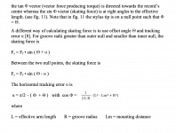
For a Birch type tonearm it is unrealistic and unpractical to calculate with effective length or the (nonexisting) overhang. So I calculated with the formula I wrote on the illustration in #11.
Klaus Rampelmann quoted the same formula (see here) from Randhawa, “Pickup arm design techniques”, Wireless World, March 1978, p.73; April 1978,
p.63.
The skating force is according to physics and the formula a function of the radius of the Thales circle of a Birch type tonearm. If the radius of the Thales circle would be infinite, the tonearm would be a tangential tracker with zero skating force.
I will answer the first question later.
Last edited:
Is this the formula you were talking about? Please see attached image. For my 6B, tracking error is not 100% zero but it is very small and in a very short distance. Its maximum value is less than 0.1 degrees. It is reasonable to assume tracking error is zero. The offset angle is zero, too. If someone thinks the offset angle for a Birch arm is the angle between arm wand and its pivot, no problem, the offset angle varies across the surface of the record.
Attachments
Last edited:
Ok. Here is your formula.
Fsk=Ffr sin(α)
For my 6B, α=0. sin(0)=0
Fsk=0.
Skating force is 0.
Is this correct?
Fsk=Ffr sin(α)
For my 6B, α=0. sin(0)=0
Fsk=0.
Skating force is 0.
Is this correct?
Klaus Rampelmann in his article said:
Although he mentioned 2 PT arms, he didn't present any formula to calculate the skating force of Birch arms.
Fs =Ff •sin(Θ+α)
Above formula is for regular pivot arms only. For a Birch arm such as my 6B, both Θ, offset angle (if you want to use the angle between arm wand and pivot link), and α, tracking error ( if you insist that tracking error is not zero even the tracking error is very small) vary across the surface of the record.
Is there any formula for calculating the skating force of Birch arms? According Wally Tools' in the comment section of this link
Everything You Know About Skating Is Wrong! | Analog Planet
However, I haven't seen such calculation yet.
As long as the line connecting the stylus tip to the arm pivot is not tangential to the groove at the contact point, which is always the case for pivoted arms, a skating force is generated. For that very reason tangential pivoted arms like the Garrard Zero and the Thales still have anti-skating mechanisms.
Although he mentioned 2 PT arms, he didn't present any formula to calculate the skating force of Birch arms.
Fs =Ff •sin(Θ+α)
Above formula is for regular pivot arms only. For a Birch arm such as my 6B, both Θ, offset angle (if you want to use the angle between arm wand and pivot link), and α, tracking error ( if you insist that tracking error is not zero even the tracking error is very small) vary across the surface of the record.
Is there any formula for calculating the skating force of Birch arms? According Wally Tools' in the comment section of this link
Everything You Know About Skating Is Wrong! | Analog Planet
Granted, such tonearms experience a good deal less skating force at the record extremes than do typical pivoted tonearms across the entire record, but they still experience skating force - in BOTH directions. Skating force on these arms decreases steadily from the record extremities until they reach zero when the stylus lands on the point of perfect tangency. You can see this in action on the videos.
Tangential pivoted tonearms probably do a good job without anti-skating at preserving the stylus by providing uneven wear at the outside of the record against the right channel facet of the stylus and uneven wear at the inside of the record on the left channel facet. This may balance stylus wear, but what about the grooves of the record???
I don't have the answer to that question, but I know it is certainly calculable. Alas, my priorities are not there right now as I've got coefficient of friction on my table right now. WallySkater owners deserve those results and I am aiming at them.
However, I haven't seen such calculation yet.
Last edited:
1, Please see the image. The main conflict between your calculation and Kogen’s calculation is when the skating force reaches its maximum level. For a regular pivot arm, yours is at the most inner groove while Kogen’s is at the most outer groove.
?
As promised, I answer your first question: you are right, the curve has to be flipped horizontally. I got lost in the spreadsheets.
Attachments
- Home
- Source & Line
- Analogue Source
- Building a Tuthill/Reed 5A Tangential Tracking Pivot Tonearm