Ok. Here is your formula.
Fsk=Ffr sin(α)
For my 6B, α=0. sin(0)=0
Fsk=0.
Skating force is 0.
Is this correct?
No. With Birch type tonearms, you have to calculate with the angle between the tangent to the path of the stylus and the line from the stylus to the spindle. With traditional tonearms, this is equal to the angle written in Rumpelmann's article.
Last edited:
Ok. As I told you that my 6B has less than 0.1 tracking error at certain points, and the tracking errors starts at the most outer groove with 0 tracking error, then it increases to 0.1 degrees at a point. After a short path, it decreases to 0 again until the end of the groove. It varies cross the surface of the record. By the way, this is the reason why Frank used a non-circle guiding rail for his LT tonearm.
How do you calculate such a dynamic process? Does the process reflect in your formula?
How do you calculate such a dynamic process? Does the process reflect in your formula?
Last edited:
In addition to my comments above, you took offset angle out from Rumpelmann's equation without any considerations. It is completely wrong and unnecessary. Even using original formula, offset angle is zero for my 6B.
I don't know how to do the math but I am confident that when it comes to skating force in a hypothetical frictionless arm the main pivot, the fixed static one that's supporting majority of the mass, should be as close to the Thales locus as possible to achieve the least skating force. And if the main pivot is located at the locus, it would have zero skating force. Oftentimes that renders the vertical arm being very long, the Schroder LT being the longest even if it still has some residual skating force. Long vertical arm might be less desirable to low bending mode school of thoughts so your mileage may vary. Of course, there are ways to design a shorter vertical arm WITH a long horizontal arm. I guess all designers have to make these decisions to arrive at their desired outcome.
I don't think low tracking error geometry in a Birch arm is a challenge anymore. The creativity comes from choosing the balance between lengths of the vertical arm and horizontal arm and along with, of course, bearing designs. This is an exciting time in the tangential tracking options!
I look forward to 2wice/Trenton's simulation results.
In addition to my comments above, you took offset angle out from Rumpelmann's equation without any considerations. It is completely wrong and unnecessary. Even using original formula, offset angle is zero for my 6B.
Not true. I took out the tracking error. This is the answer to your next question too.
As I wrote, the offset angle in traditional tonearms is equal to the angle between the tangent to the path of the stylus and the line from the stylus to the spindle (+tracking error), so I did not "take it out".
End of discussion.
I don't know how to do the math...
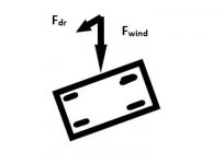
It is not rocket science. Let's take a frictionless wagon on which the wind blows and exerts a force Fwind.
The angle α between the wheels and the direction of the wind is 110 degrees. What is the magnitude of the force Fdr which drives the wagon?
Fdr = sin (α-90) x Fwind
Same with stylus.
Excuse the drawing.
Attachments
Not true. I took out the tracking error. This is the answer to your next question too.
As I wrote, the offset angle in traditional tonearms is equal to the angle between the tangent to the path of the stylus and the line from the stylus to the spindle (+tracking error), so I did not "take it out".
End of discussion.
Now, it is getting even worse.
Fs =Ff •sin(Θ)
Θ is offset angle. Θ=22 degrees.
sin(Θ)=sin(22)=0.374
Fs=Ff •0.374
For pivot arm, its skating force is constant. Clearly, it is not correct.
In any cases, I appreciate your efforts to calculate the skating force of my 6B. However, the formula you used is NOT for PT arm at all.
Last edited:
I want to emphasize again. It really doesn't matter what you took out or what you added in, the formula in the article by Klaus can't be used for calculating the skating force of PT arms without modifications. If you want to use this formula, you have to understand clearly about effective length, tracking errors, and offset angle for PT arms, and establish the relationships between these factors.
Last edited:
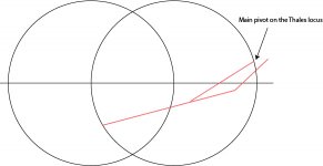
I don't know how to do the math but I am confident that when it comes to skating force in a hypothetical frictionless arm the main pivot, the fixed static one that's supporting majority of the mass, should be as close to the Thales locus as possible to achieve the least skating force. And if the main pivot is located at the locus, it would have zero skating force.
I am not sure what you mean. Please see attached image. Does this image represent your view correctly? The main pivot is on the Thales locus.
Attachments
However, the formula you used is NOT for PT arm at all.
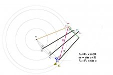
How to calculate the skating force Fsk of a PT arm?
There is a virtual pivot at the center of the Thales circle, otherwise the stylus would not move on the circle.
The torque of the friction force Ffr has to be calculated by multiplying it with the distance from the center.
Attachments
Now, it is getting even worse.
Fs =Ff •sin(Θ)
Θ is offset angle. Θ=22 degrees.
sin(Θ)=sin(22)=0.374
Fs=Ff •0.374
For pivot arm, its skating force is constant. Clearly, it is not correct.
In any cases, I appreciate your efforts to calculate the skating force of my 6B. However, the formula you used is NOT for PT arm at all.
Come on. For a traditional arm, the tracking error must be taken into the formula too. It is partly positive, partly negative, and constantly changing, so the skating force can not be constant. This is in accordance with what Rumpelmann and I wrote.
With a PLT arm the tracking error is less than the fabrication and adjustment tolerance so it is negligible.
How to calculate the skating force Fsk of a PT arm?
I don’t know.
There is a virtual pivot at the center of the Thales circle, otherwise the stylus would not move on the circle.
The torque of the friction force Ffr has to be calculated by multiplying it with the distance from the center.
It is getting messy. If the stylus moves on the Thales circle perfectly, it means the tracking error is zero. So, in your formula,
Fsk=Ffr sin(α)
For my 6B, α=0. sin(0)=0
Fsk=0.
Skating force is 0.
But you said it is not correct because there are tracking errors. If there are tracking errors, it means the stylus doesn't move perfectly following Thales circle.
I have to put a stop here. Otherwise, it wastes time. You need to study PT arms and get better understanding about PT arms before you try to calculate its skating force.
Last edited:
You need to study PT arms and get better understanding about PT arms before you try to calculate its skating force.
Not necessary, if you have the effective length, then you have the "offset" and can calculate it. I suspect you don't know your arm's effective length.
First, you need to forget that the stylus is on the Thales circle, it means nothing.
Not necessary, if you have the effective length, then you have the "offset" and can calculate it. I suspect you don't know your arm's effective length.
First, you need to forget that the stylus is on the Thales circle, it means nothing.
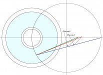
That is a good question. What is the effective length of a PT arm? Please see the image. I take the geometry of my 6B as example. Everything is about my 6B arm in order to avoid any confusions.
The green and red lines are traditional definitions of effective length. The blue line is non-traditional definition of effective length. For the blue line, its pivot is a virtual pivot. All these three effective lengths vary.
Furthermore, what is the offset angle for a PT arm? By traditional definition, there is no offset angle for a PT arm for my 6B. However, if we can define the offset angle in non-traditional sense, there will be two offset angles, A and B as in my drawing. The offset angles vary cross the surface of the record.
Yes. Everything can be calculated. But not in the way what alighiszem tried to do.
If we try to discuss that topic further, we need to have agreement what is the effective length for a PT arm. Frankly speaking, I don't form an opinion so far although I lean toward the blue line as the effective length for a PT arm. So, what is the offset angle for the blue line? I don't form an opinion either.
What I was trying to say is the formula used by alighiszem can't be used for calculating the skating force of my 6B without any modifications.
Attachments
Last edited:
Your effective length is the green line, it is the outermost and 1st fixed pivot in the mechanism.
The offset is the acute angle between the green and blue lines, not the angles marked, it gets smaller approaching the spindle, not bigger.
Very easy to test, align the force vector with each of the lines and the one that does not move is your effective length.
I've done blue already.
The offset is the acute angle between the green and blue lines, not the angles marked, it gets smaller approaching the spindle, not bigger.
Very easy to test, align the force vector with each of the lines and the one that does not move is your effective length.
I've done blue already.
Very easy to test, align the force vector with each of the lines and the one that does not move is your effective length.
I may not disagree with you for my 6B. But it means that every PT arm has its own, individual effective length. Things may get complicated even for the PT arm with same geometry as my 6B. Even for my 6B, the primary pivot ( green line) can be secondary, too. If the secondary pivot (red line) carries the total mass of the arm, the red line becomes the effective length. Or, both pivots can equally carry the total mass of the arm. What will happen? Which line is the effective length?
Last edited:
But it means that every PT arm has its own, individual effective length
Correct
Things may get complicated.
The underlying factors remains the same.
Correct
It may mean that different PT arms have different skating behaviors.
It may mean that different PT arms have different skating behaviors.
Yes, as do pivoting tonearms with different geometry.
- Home
- Source & Line
- Analogue Source
- Building a Tuthill/Reed 5A Tangential Tracking Pivot Tonearm