I updated my original post, but I thought I would add it here as well. The matched pair: JFE2140, is now available on ti.com: JFE2140 data sheet, product information and support | TI.com
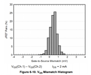
Mismatch between VGS (spec'd at 2mA drain current) is 4mV max. IDSS of the two JFETs is spec'd to match within 5% (min/max).
Mismatch between VGS (spec'd at 2mA drain current) is 4mV max. IDSS of the two JFETs is spec'd to match within 5% (min/max).
I updated my original post, but I thought I would add it here as well. The matched pair: JFE2140, is now available on ti.com: JFE2140 data sheet, product information and support | TI.com
Mismatch between VGS (spec'd at 2mA drain current) is 4mV max. IDSS of the two JFETs is spec'd to match within 5% (min/max).
Nice John, thanks TI. Like that the so package is pin compatible with the LSK389. And the lower price
")
And with the half transconductance I asked for, resulting in lower input capacitance. Perfect fit for a couple of future projects.
Last edited:
That is worse than Toshiba decades ago where 2SK389 / 2Sj109 are specified at 3%.
The majority of them measured below 1% actually.
I am sure TI can do better.
Patrick
We specify our datasheet min/maxs 6 standard deviations away from the mean for a parameter like this, which means its an extremely conservative limit. Most companies are nowhere near as conservative, but when you have a non-obsolescence policy like TI, you have to be conservative to ensure you can meet the datasheet limits over multiple decades at high production yields.
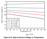
I think figure 6-8 in the datasheet is the closest to what you're asking for. It plots the VGS vs temperature for a given drain current. Looks like about 5mA of drain current is the closest to a zero tempco. Interestingly, at the highest drain current (10 mA) the tempco is positive, while the lower drain currents show a negative tempco.
Attachments
I updated my original post, but I thought I would add it here as well. The matched pair: JFE2140, is now available on ti.com
Hi, John!
Hi, Mike!
Please, let us know, you know first hand all the people's hopes, are there a possibility to see matched quad 2n+2p in something like DIP14 case?
Hi Patrick,
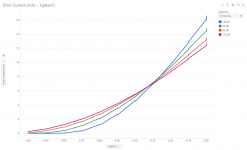
I compiled the data for one unit in the format you asked for here, let me know if this is what you are looking for.
Many thanks.
Best regards,
Patrick
Hi, John!
Hi, Mike!
Please, let us know, you know first hand all the people's hopes, are there a possibility to see matched quad 2n+2p in something like DIP14 case?
We've certainly talked about P-channels internally, along with many other possibilities. Since this is a new foray for us I think we're waiting a bit to see how successful these devices are before going further down this path with more.
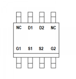
If we did matched P/N JFETs I think we'd need to decide what matching really means, since the devices are structurally very different and hence any "match" is always partial. And I can pretty much say with certainty we wouldn't do it in a DIP-14. SOIC-14 would be likely though.
N-P matching means different things in different applications. For a complementary input even if you get matching Gm the capacitance and speed will be quite different. While you could make them on the same substrate it may be better to have different silicon for N&P. And if you are using them as complimentary switches (e.g. DA converter) you would want a different matching, like Rds on.
Are these made on the big (12"?) wafers with the high res masks?
Are these made on the big (12"?) wafers with the high res masks?
Why do people ask for complementary quads ?
Take a look at section 3 & 4 here :
Distortion in JFET input stage circuits
See also :
F5 power amplifier
I agree with Demian.
If I can wish, I rather have separate NN & PP.
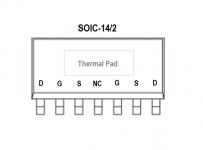
Not in SOIC 8, but a half SOIC14 with 7 legs on one side, like the 2SK389. And with thermal pad.
The clamping diodes is not really must-have in analog audio.
Patrick
Take a look at section 3 & 4 here :
Distortion in JFET input stage circuits
See also :
F5 power amplifier
I agree with Demian.
If I can wish, I rather have separate NN & PP.
Not in SOIC 8, but a half SOIC14 with 7 legs on one side, like the 2SK389. And with thermal pad.
The clamping diodes is not really must-have in analog audio.
Patrick
We've certainly talked about P-channels internally, along with many other possibilities. Since this is a new foray for us I think we're waiting a bit to see how successful these devices are before going further down this path with more.
Ok.
If we did matched P/N JFETs I think we'd need to decide what matching really means, since the devices are structurally very different and hence any "match" is always partial. And I can pretty much say with certainty we wouldn't do it in a DIP-14. SOIC-14 would be likely though.
Let me input my fifty cents.
Matched dual-N are a good part, doesn't regard of tightness of thermal matching.
All of this are strictly aimed to the input differential pairs, so the "matching" are better to read as "transconductance matching at a same ~1/2 Idss current and better if at a given zero tempco point". As for audio, this can be near ~5mA and ~60 celsius degree.
Of course, your fab provides you with different Idss crystals and for yield using purposes you will have different tolerance matching.
So, two classes of grades, no way.
First class is for Idss, say 1-3 mA, 3-7 mA, 7-12 mA and 12-20 mA, for example, or more.
Second class is for matching, graded as CMRR, say in dBs.
Of course nonlinear price scale.
SOIC are good enough too, ok, even TSSOP.
N-P matching means different things in different applications. For a complementary input even if you get matching Gm the capacitance and speed will be quite different. While you could make them on the same substrate it may be better to have different silicon for N&P.
Yes, capacitances will be differ, like 2x or so. But as for complementary input it feeds from relatively low impedance sources (let's exclude mic preamps and talk about audio amplifier/preamplifier cases), an orders of not higher than 3-5 kOhm. And even with 100 pFs those parts will be far away from suffering widebandness.
Why do people ask for complementary quads ?
Good question, Patrick, this is because they actually forms relatively good self-biased stage and doesn't needs anymore additional.
Just match their transconductance at a working current and working temp.
And if you are using them as complimentary switches (e.g. DA converter) you would want a different matching, like Rds on.
On, no, this is a very different question and i doubt it needs NN-PP matched quads.
Last edited:
The JFE2140 is a very interesting part.
The noise is only specified as typical. I think it was mentioned earlier that there were no plans to test for noise during production. Will the maximum noise be "tested" indirectly to make sure that the noise is not way off? Small deviations can of course be accepted, but without a maximum it is a bit of a gamble, unless the part will be rejected for some other reason. Or the process ensures that they all perform well of course.
I focus on this because I have seen some very bad examples with the LSK389. A relatively high percentage had noise levels way above the normal level and I had to replace them. I even had to replace one noisy LME49990 in the same design, but even though it was noisy, it was nowhere near the problem seen with the LSK389. Linear Systems seem to have introduced a test for noise in production, so hopefully the problems with the LSK389 have been solved.
I know that it probably adds quite a lot of test time to do this test, but it would be nice to have some assurance of the performance.
- Home
- Vendor's Bazaar
- Ultra Low Noise JFETs from Texas Instruments