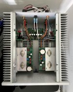
Measure from ground to the screw circled in this image.
That did it!!! Thanks so much for the visual aid, it helped this rookie. I appreciate the help immensely. I will put the case back together and see how it sounds.
Thanks again and I will let you know the progress.
Measure from ground to the screw circled in this image.
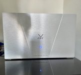
Got it up and running. Using an old 70's Luxman receiver's pre-outs and it is silent with no weird audio irregularities. More importantly, it sounds great. There's more detail than I was expecting and the tone is great. Going to play with some tomorrow.
Thanks again, everyone!
Attachments
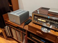
try direct to a dac ....pc volumeGot it up and running. Using an old 70's Luxman receiver's pre-outs

LOL! I was thinking the same thing, not the most subtle of tools for such a delicate Amp!I wonder what the wrench was used for (on top on Luxman).
")
Neil
don't panic!
Systematically check
- V+ on the left channel output board
- Ground on the left channel output board
- shortage on the output?
It could also be helpful, when you post some pictures.
Franz
One channel dead
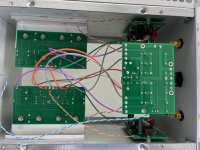
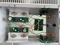
Thanks Franz. I have attached a couple of photos of the amplifier. I haven't spotted any wiring mistakes. I have made the following voltage measurements; Good Channel - MOSFET Drain 14v, V+ 33.9v, +0 0.035v, VFET case 33.96v, Z1 A 7.7v, Z1 C 14.0v, Z2 A 1.3v, Z2 C 6.00v. Bad Channel - MOSFET Drain 14v, V+ 35.88v, +0 0.024v, VFET case 35.88v, Z1 A 2.85v, Z1 C 13.44v, Z2 A 0.06v, Z2 C 2.89v.
I have tried a transistor tester on both mosfets and vfets (peak design) but don't get reliable readings.
Any thoughts re MOSFET or VFET would be greatly appreciated.
Neil Meredith
Attachments
Nelson, thank you for your altruism and generosity. Jason and Elena thank you for such a good job with the store and bulletin board. VFet the most exciting thing in 2021!
I've been building 172 but have hit a problem. Completed the build with care as per guide and Nelson's notes. Got a DPST switch in no problems. Checked wiring 3x. Powered up and tweaked bias to 14v and adjusted after warm up no problems. Heatsink and bracket temperatures felt right. Wonderful Eva Cassidy. Then from L channel fizzing sound and L channel goes quiet, just quiet distorted sound, other channel fine. Bias has changed to 17v possible to rebias to 14v though. Has the worst thing in the world happened and the VFet has died? Also no longer heat generated from L channel. Checked and rechecked wiring all seems good. Gentle advice would be very welcome.
Neil M
what is Iq now, measure voltage across R1 or R2
worth a try - replace 4N35, check resistors connected to it
if that isn't helping, remove mosfet and check it with simple matching jig
all in hope that VFet is ok, and fact that you can vary output node voltage is implying that, same as that biasing parts are OK
just to amuse us, post proper macro pic of Dodo channel pcb
if that isn't helping, remove mosfet and check it with simple matching jig
all in hope that VFet is ok, and fact that you can vary output node voltage is implying that, same as that biasing parts are OK
just to amuse us, post proper macro pic of Dodo channel pcb
Number 82 is Running
Thank you Mr. Pass and everyone else involved in this amazing opportunity.
What a wonderful sounding amp! All of my Pass amps sound great,
love them all but this one is very special as in literally gives me goosebumps special.
Aside from that, I am speechless.
Thank you all again.
-Bill
Thank you Mr. Pass and everyone else involved in this amazing opportunity.
What a wonderful sounding amp! All of my Pass amps sound great,
love them all but this one is very special as in literally gives me goosebumps special.
Aside from that, I am speechless.
Thank you all again.
-Bill
Attachments
it is so rude, having both Ducati and VFet amp

Well then this isn't going to help my cause.
Attachments
Last edited:
it is so rude, having both Ducati and VFet amp
@bbm3no 992 no party I ZM suggestion for alternative psu filter resistor ?
smell too much for my taste in bedroom...
Last edited:
- Home
- Amplifiers
- Pass Labs
- DIY Sony VFET pt 2 (N-Channel Build)