@ MEPER
Or don't buy them = save money and test Vfet's directly with DIY Audio kit chassis heatsink ?
Or don't buy them = save money and test Vfet's directly with DIY Audio kit chassis heatsink ?
I only have the VFET amp (assembled).
I have not noticed a kit chassis heatsink for sale......but will have a look.
The other stuff was like 15 USD.....
I have not noticed a kit chassis heatsink for sale......but will have a look.
The other stuff was like 15 USD.....
Assembled ok but You can take out the one channel pcb and test Vet's 3 pcs. on this heatsink with T bracked.
Easy..cost 0$..no need shipping and ecologicaly friendly..winner & winner 🙂
Easy..cost 0$..no need shipping and ecologicaly friendly..winner & winner 🙂
..The other stuff was like 15 USD.....
Heatsink looks tiny..if you want serious high quality device under test jig ( Mosfets, Vfet's, Tokin's )
for Your future mesurements then go buy large one , similar to 25 Watt's class A amp size 🙂
The T-bracket idea could be used for a test jig. Then a "normal" large heatsink can be used.
I may just put the new KF-33 in the amp and see what happens. I feel confident that it works ok.
I may just put the new KF-33 in the amp and see what happens. I feel confident that it works ok.
Trust your ears to tell you if it’s Ok.
Allow for at least 20 hours of run-in. 100 hours better still
Allow for at least 20 hours of run-in. 100 hours better still
V-fet 052 is up and running. Due to health issues I just built this amplifier. It was one of the easiest FW amplifier I have built and I have built just about all of them. Voltages were pretty much on the money on startup. Just a slight touch of the pots got them at 20V. Plan on doing some listening tonight. No issues so far.
Heatsink looks tiny..if you want serious high quality device under test jig ( Mosfets, Vfet's, Tokin's )
for Your future mesurements then go buy large one , similar to 25 Watt's class A amp size 🙂
I went for the cheap heatsinks and I may use two in a "piggy-back". I can always use a fan during testing with a lot of power.
I have seen the "ZM-tower" when ZM are testing his amps. I have limited space and already have too much stuff around.
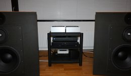
The two ACA's are in service now until VFET is ready again. I also just installed a STA-1000D class D amp for the 15" woofers. It makes a difference. ACA gets much nicer working condition and I can play very load without sound gets compressed. Will also be nice for VFET.
The spec. for STA-1000D says damping factor = 1000 ? ....so some kind of control is expected. It is only for bass control.....not for "music".....unless it is for a party. Probably a nice "party-amp".
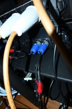
The STA-1000D has only SpeakOn out so I needed to build a small converter from SpeakOn to banana-plugs. It works well.
Think I will just try to drop the spare KF-33 in VFET amp and see what happens. Can do that while watching UCI World championship.....
Attachments
@ MEPER
Anyway You right this flickering noise can be detected only by playing amp with new Vfet 🙂
Have a nice Sunday
Anyway You right this flickering noise can be detected only by playing amp with new Vfet 🙂
Have a nice Sunday
Thank you!
I just realized that the original is a KE-33.
Good I also have one of those.......
I just realized that the original is a KE-33.
Good I also have one of those.......
Checking temps I notice that one of my Q3 transistors is running really hot 80c. The other is much lower 45C to 50c. Voltages are the same comparing the leads of both of them. In the article by NP he states Q3 regulates the current for Q2. Obviously there is too much current going through Q3. Possible Q2 problem? Max temp for the 4N35 is 100C. Plays fine with no problems but concerned. Any suggestions, opinions appreciated.
I just started an auction for one pair of 2SK82 wich I purchased from Acronman in 2012.
ebay article number 265309170763
And now I started another auction for my second and last pair of N-channel Sony Vfets 2SK82
ebay article number 265330878619
Good luck!
Franz
Checking temps I notice that one of my Q3 transistors is running really hot 80c. The other is much lower 45C to 50c. Voltages are the same comparing the leads of both of them. In the article by NP he states Q3 regulates the current for Q2. Obviously there is too much current going through Q3. Possible Q2 problem? Max temp for the 4N35 is 100C. Plays fine with no problems but concerned. Any suggestions, opinions appreciated.
Do you know that it is too much current?
It could also be that it is too loose against the heatsink so maybe check the tension?
My guess of too much current is due to voltages on the pins of the 4N35 are the same on both channels so not a voltage problem. Working OK so the hot running 4N35 should last a few years as is but I would like to bring the temp down if possible.
wdecho
compare voltages (between channels) across R1 (or R2)
if these are the same and if you can set output node voltage same on both channels, at least amp is functional as needed, in OS department
check small resistor values, these connected to 4N35 ..... and be sure that you determine temperature in at least two ways
if using red dot gun thingie ........ I don't trust in these, only good for big areas and of not tricky emissivity
when in doubt, I'm using DVM with contact sensor
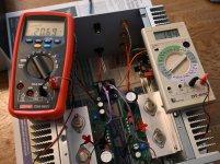
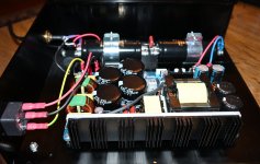
New KE-33 is now inserted (left channel) and without any adjustment voltage is close to 20 VDC between the two test points.
I also built a new PSU for the amp. Some days ago I glued 6 x small additional heatsinks using thermal glue to be sure temp is "safe". It helped a lot.
There is a possibility to adjust voltage. I measure 35.3 VDC at VFET amp board. Should I adjust it to 36 VDC or just let it be as-is and just finetune voltage to 20 VDC?
Attachments
The important bit is regulated voltage.
I doubt 0.7v difference really changes things as long as you adjust to 20V (which might not even be far off). I read here somewhere that absolute PS voltage wasn't that sensitive, as long as regulated.
Further, The original Mc Coy hasn't 36V at the VFETs. 36V is what comes out of the Mean Well, the std filter takes nearly 2 tenth of volts away, you can calculate that easily...
Have fun and let us know how it sounds
Claude
EDIT : and the latest VFET filter board for the "other" VFET even more, but then that's a different fish
Last edited:
wdecho
compare voltages (between channels) across R1 (or R2)
if these are the same and if you can set output node voltage same on both channels, at least amp is functional as needed, in OS department
check small resistor values, these connected to 4N35 ..... and be sure that you determine temperature in at least two ways
if using red dot gun thingie ........ I don't trust in these, only good for big areas and of not tricky emissivity
when in doubt, I'm using DVM with contact sensor
Everything checked OK. Beginning to not trust red dot gun either. Put top on and will find something else to worry about. Did scope both channels and everything seems to working fine. One thing though others may have noticed. After listening for 30 minutes or so I heard a loud pop coming from amp. Jumped up to see what blew but music still played great and no smoke. Finally figured it was heat expansion from case. Did some loosing and tightening screws and put top on so hoping it does not happen again.
just check them optos with tip of your finger
leave gun thingie near boiler or wherever, where it belongs
one thing - I'm using split washers practically everywhere - since I got that habit, generally less surprises (including heat expansion phenomenons )
luckily, being taught that on someone else's mistakes
 considering list of my own ookoops, nice one, for change
leave gun thingie near boiler or wherever, where it belongs
one thing - I'm using split washers practically everywhere - since I got that habit, generally less surprises (including heat expansion phenomenons )
luckily, being taught that on someone else's mistakes
considering list of my own ookoops, nice one, for change
Last edited:
- Home
- Amplifiers
- Pass Labs
- DIY Sony VFET Builders thread