Like the attached. I think they did that in my TT.
Kind of XLR-Pin1 problem without XLRs? 😀
You are using a separate wire from preamp case to TT chassis, right?
So because of that important wire, cut that short piece of wire in your picture connecting the TT chassis to one of the two RCA sockets.
Then measure the still disconnected TT between the cold side of both RCA sockets and TT chassis whether there is still a connection.
If not, both channels are now floating and should give the same response without Diazepam.
Hans
Yes, I removed the fixed/internally connected OEM phono cable and installed a RCA female jack box on the rear of the plinth. I don't remember seeing a TT ground wire link to just one of the cart channel's shield but my PE measurements indicate that it's there on the Left where the Right seemed to float. I have to wonder why this is done. It doesn't obviate the need for grounding the TT's "ground wire". There's still hum without it. Seems to me the cart's R&L voltage generators should be floating entities.
Now, if I find and remove that link won't my Left channel start behaving like the worse-behaving Right channel? More and more it's looking like I SHOULD take the TT to the O-R and look under the hood. It's a PITA 🙁
Btw, the MDN would still be needed in any case.
opa1656 has offset voltage that varies with the input Z. 47k no cart 1500 ohms cart in
you are hearing a few mV of offset being amplified to a few volts when the TT switches.
this is what a input capacitor removes.
If you haven't already, please go see post #73. It's the no cart, no TT, just a 1K terminated 4ft cable with a "mute" switch experiment. IOW, we tested the 1656's reaction when its + input was 47K//1K and then goes to 0ohms - and then back the other way.
Yes, I removed the fixed/internally connected OEM phono cable and installed a RCA female jack box on the rear of the plinth. I don't remember seeing a TT ground wire link to just one of the cart channel's shield but my PE measurements indicate that it's there on the Left where the Right seemed to float. I have to wonder why this is done. It doesn't obviate the need for grounding the TT's "ground wire". There's still hum without it. Seems to me the cart's R&L voltage generators should be floating entities.
Now, if I find and remove that link won't my Left channel start behaving like the worse-behaving Right channel? More and more it's looking like I SHOULD take the TT to the O-R and look under the hood. It's a PITA 🙁
Btw, the MDN would still be needed in any case.
So you have cut that short blank wire that was connecting the TT chassis to the cold side of one RCA socket, but one channel is still showing a connection to the TT’s chassis while the other is floating, right ?
Well in that case it is most likely the Cart that has a connection between it’s body and the cold side of one channel.
When you can remove the shell from your arm, you will see that there is no longer a connection. When you don’t have a removable shell, you can disconnect the wires from the Cart to get a confirmation that the connection is made on the Cart.
Hans
I was being sarcastic, but in fact it's not funny at all.
Actually I don't even know why RCA connectors are even a thing in "high end audio", there's no such thing as "ground level". Just repeating Bruno Putzeys' the g-word arguments here, but I think he is soooo right...
Get your grounding scheme right.
Get your gain structure right.
Live happily ever after.
😀
Of course I knew what you meant. I think the way the grounding was done in that turntable is not correct.
If that is by Mr. Putzeys I think he is absolutely right 🙂
Get your grounding scheme right.
Get your gain structure right.
Live happily ever after.
If that is by Mr. Putzeys I think he is absolutely right 🙂
Last edited:
If that is by Mr. Putzeys I think he is absolutely right.
No, that's a summary by me. First line stems from Bruno's very valuable insights.
Second line is one of my key points. No point in amplifying signals to unneeded levels and then attenuating them again in the last stage, usually the PA. get your gain structure right and you will a) be able to crank your volume control to 10 and nothing will break (not ELEVEN! 😉) and b) SNR will be at it's very best.
live happily ever after - that was an unnecessary addendum 🙂
PS: regarding gain structure. most modern power amplifiers have their THD+N minimum near full power. Choose a power amplifier that is not oversized and you will be better off at low listening levels as the PA is closer to it's optimum workling conditions. That's why I chose a 10-15W PA, a LPUHP clone for my flat's living room where 6x 10W can be VERY annoying to neighbours, so nothing more is needed. In fact the usual 100mW to 1W will perform much better than any 100W+ amplifier at these levels.
Last edited:
Then I agree with you. Call the newspaper!
Not calling anybody. Just my humble opinion. If I wanted to be a preacher - well I would have a very different job to a software engineer 😉
So you have cut that short blank wire that was connecting the TT chassis to the cold side of one RCA socket, but one channel is still showing a connection to the TT’s chassis while the other is floating, right ?
Well in that case it is most likely the Cart that has a connection between it’s body and the cold side of one channel.
When you can remove the shell from your arm, you will see that there is no longer a connection. When you don’t have a removable shell, you can disconnect the wires from the Cart to get a confirmation that the connection is made on the Cart.
Hans
No. I didn't mean to indicate I was going to jump right on that. Requires some resolve. And just to re-calibrate your thoughts can you review post #73 test I did without the cart or TT attached. Should be here:
OPA1656 Phono Preamp: Split from OPA1656 thread
And a simplified sketch of what was done is attached as PDF. It leap-frogged a lot of guessing and theorizing. It ain't the cart, it ain't the hook-up, it ain't the PE and it ain't the actual mute switch. Please do try this at home! No turntable required. 😀 What it is, I'm slowly gathering, is related to the 1656 and others + this RIAA circuit topology + a semi or fully auto TT with a lift/lower muting feature OR there is something inherently BAD about my implementation. For example, there is probably 100nH all-tolled in the feedback loop including caps, short copper traces and 22ga wire jumpers. What about that bit..?
Attachments
OK, to confirm earlier - With cart removed from the tonearm there is ~12 ohms between the Left shield and the TT's ground wire. There is no connection between the Right shield and the ground wire. Don't know where that 12 ohms happens yet. The cart body is plastic so there is no head shell connection.
Tonight I mounted the Denon DL-110 - a very long-running High-Output Moving Coil design (HOMC). Very popular. Output is 1.6mV vs. the Audio Technica MM 4mV and the 1656 preamp handles that diff just fine. The Denon is supposed to be compatible with MM phono stages. Inductance is not published. Output impedance = 160 ohms which is supposed to mate to the very standard MM load of 47K. Lots of online chatter re what it really likes best. Just FYI re the diazepam fix provided by Marcel.
Tonight I mounted the Denon DL-110 - a very long-running High-Output Moving Coil design (HOMC). Very popular. Output is 1.6mV vs. the Audio Technica MM 4mV and the 1656 preamp handles that diff just fine. The Denon is supposed to be compatible with MM phono stages. Inductance is not published. Output impedance = 160 ohms which is supposed to mate to the very standard MM load of 47K. Lots of online chatter re what it really likes best. Just FYI re the diazepam fix provided by Marcel.
What it is, I'm slowly gathering, is related to the 1656 and others + this RIAA circuit topology + a semi or fully auto TT with a lift/lower muting feature OR there is something inherently BAD about my implementation. For example, there is probably 100nH all-tolled in the feedback loop including caps, short copper traces and 22ga wire jumpers. What about that bit..?
Hence my question to johnc124, which he hasn't answered yet.
100 nH from output to negative input and 100 ohm in the branch from the negative input to ground results in a 1 ns time constant, so a cut-off frequency of about 159 MHz. That's above the gain-bandwidth product but not by decades, so it will reduce the phase margin - by about 7 degrees to be specific.
Last edited:
Maybe it would, and maybe it wouldn't help, I don't know. Hence my question to John about the real part of the input impedance of OPA1656 voltage followers with a perfect board layout.
It certainly will not be worse. IMO using modern fast opamps on perfboard is asking for trouble.
I just thought of the simple design choices Audio & Techniek used to make. A DIL switch (gold plated contacts) with various value caps that could be paralleled to the 47 kOhm. Way simpler to adjust than soldering in and out of caps.
I just thought of the simple design choices Audio & Techniek used to make. A DIL switch (gold plated contacts) with various value caps that could be paralleled to the 47 kOhm. Way simpler to adjust than soldering in and out of caps.
Last edited:
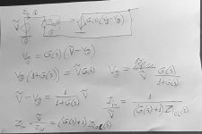
I've made a simplistic attempt to answer my own question, and I think you can get a negative input resistance with just about any op-amp, even without any board parasitics.
In the attachment G(s) is the open-loop gain and Ziol(s) is the open-loop input impedance. The closed-loop input impedance turns out to be (G(s) + 1) Ziol(s). The open-loop input impedance will normally be largely capacitive and the gain plus one factor will also have a negative phase, so the phase of the closed-loop input impedance will be beyond -90 degrees, resulting in a negative real part.
Of course this doesn't mean that an imperfect board can't make it worse, only that you don't need a bad board to get a negative input resistance.
Attachments
Last edited:
- Home
- Source & Line
- Analogue Source
- OPA1656 Phono Preamp: Split from OPA1656 thread