1) I will replace this zobel capacitor with a bigger one.
2) The output post isn't in the line of emitters tracks yet. You mean it would be better even farther from that? About FB takeout: You're right. However it will tricky a bit to redraw it.
Thank you.
2) The output post isn't in the line of emitters tracks yet. You mean it would be better even farther from that? About FB takeout: You're right. However it will tricky a bit to redraw it.
Thank you.
Signature motto: inspired by Ramcres. Listening to AH578, I am increasingly convinced that one of the biggest problems with solid state amplifiers is a "subtle time distortion". Your amps effectively reduce this.
3) These 45 Ohm resistors, in real build most likely gonna be 47 Ohm
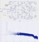
Thank you. Even more symmetric current distribution. while keeping 20k resistor >> less current stress on the LEDs. the FFT profile looks like this now before clipping. Not bad either. The phase sift at 20kHz is less than 5°.
Attachments
I think this will be the final board.
Attachments
Last edited:
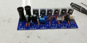
My 1st PCB is completed, now moving on to the tedious task of matching mosfets..
First will try with just one pair, and then add 2nd and 3rd pair.
This time, I used bigger Zener resistors to avoid smaller ones running hot.
I should have allocated more space on the PCB for them... It's crowded..
First will try with just one pair, and then add 2nd and 3rd pair.
This time, I used bigger Zener resistors to avoid smaller ones running hot.
I should have allocated more space on the PCB for them... It's crowded..
Attachments
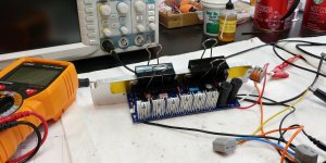
Started testing it. Something is obviously wrong.
I was supposed to start with only one pair, but in all the excitement, I soldered all 3 pairs to the PCB, and then realized I went too far.
So I 'm powering it with 50V rails, with 200mA current limiter.
Everything starts OK, green and both red LEDs are on, output dc offset is 0V.
Current draw is 100mA.
And then, slowly, over next 10s (or 15s ?), dc offset is slowly getting higher and higher until reaching -42V. I can watch it climbing volt by volt.
One red LED (bottom one) will eventually go dark.
No smoke, no heat, current draw is steady at 100mA on both rails.
Op-amps rails at 15V at all times.
I've never seen this kind of behavior.
It looks like some capacitor, somewhere is slowly charging, and causing this..
Diagnostics in progress...
Attachments
Last edited:
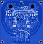
I think this will be the final board.
is the lefthand (at bottom left) zener oriented correctly?
is the lefthand (at bottom left) zener oriented correctly?
In this case, the voltage on the positive side would drop to close to 0 and the zener would become quite warm. However, according to Minek, this phenomenon happens relatively slowly and the voltage remains + -15 v on both sides of the op-amp rails.
Egra, on your pcb zener is oriented wrong.
On mine it's ok.
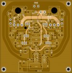
Right. There were several minor errors on my PCB. The 22 Ohms base resistors were also connected incorrectly. Here is the final one:
Attachments
Last edited:
If the op-amp supply rails are OK and there is no smoke, maybe one of the components in VAS populated improperly or damaged?
Last edited:
I didn't have time to continue debugging this amp (except for re-checking the PCB for mistakes and re-checking all soldering),
but by looking at the schematic and thinking what could have gone wrong, I noticed that this is the ONLY amp from all these LMK/Wiederhold-like 'unusual' amps, that doesn't have a resistor between the input and the ground.
Perhaps it should?
So without the signal, the (+) input of the op-amp is wide open.
So whatever DC offset is present at the output, is fed back to the op-amp, and perhaps amplified, and after 15s it grows to high value.
First thing to check tomorrow, is to short the input to the ground and see what happens.
But I have a feeling that is the reason!
In the sim without input shunt resistor, the calculations take forever, and ltspice never finishes.
With 100k resistor to the ground the sim works fine, as expected.
Egra, you may need to add that resistor to your PCB. Will check tomorrow what value is needed.
Last edited:
Input ground resistor
I think you need one, and a typical value would be 100k.
The fet input stage would be in the megohms; a ground reference for the input node is needed to refer the output offset.
One of the great advantages of the IC is that you can do away with the shunt cap on the fb divider and still maintain outstanding offset. But to achieve that offset control you have to refer the input to ground.
Right. 100k Ohm looks just right.
Also one more thing - the speed-up cap across emitters of the drivers (E.g. 1uF) might be also a good thing (assuming there is no oscillations).
It really speeds up max slew rate. Makes big difference, so I'm going to test with it.
I skipped it in the previous amp, perhaps I should add it back.
Also one more thing - the speed-up cap across emitters of the drivers (E.g. 1uF) might be also a good thing (assuming there is no oscillations).
It really speeds up max slew rate. Makes big difference, so I'm going to test with it.
I skipped it in the previous amp, perhaps I should add it back.
YES, Minek, that speed up cap helps with speedy switching of the output devices. Self talks about this in the EFII section. I have found that the type of cap here is important too; I use polystyrene for its low DF.
why not give the entire lower or upper layer to the electric ground, making partitioning on it?Right. There were several minor errors on my PCB. The 22 Ohms base resistors were also connected incorrectly. Here is the final one:
- Home
- Amplifiers
- Solid State
- HexFet Amp Based on Philips AH578 and LMK