Can also post my layout from post 162.I am planning on using Prasi’s layout from post #152 and will be driving 14 ohm headphones, do I need to make any changes?
Given that an output capacitor of 2200uF is bein GB recommend for 32 ohm headphones, should use a slightly larger value here, say 3300-4700uF?
I´d use 3.3mF. Not much to be gained above that IMHO.
I think you would have to raise the bias current of the output stage to squeeze ~100mW out of the amp with low distortion.
What headphones are these/what power do they need?
If you would make R1&R6=18Ohm and R8=12Ohm bias current would be ~ doubled at 170mA. This gives ~110mW at THD=0.002% but I´m sure that figure could be improved.
Problem now is that Q1 sees ~550mW average power dissipation,
R1&R6~500mW and R8~350mW.
These would have to be "beefed up": use 2W parts and lift them from the board.
Q1=BD139 is still fine but will have to be properly cooled.
(something like that heatsink in post #267; temperature rise would be >55K without heatsink)
Thanks chaps, the headphones are a pair of Sony DR-S5 that sound good now that I have bypassed the tone and volume controls that were all the rage back when they were made.
They seem unusually low impedance for headphones, I measured the DCR to check and they come out at 13 ohms.
I have a few vintage receivers and they are good enough to tell the differences between their headphone stages and so I’m after something better.
I am a class A convert, no issues with heatsinking, beefier transistors etc.
Thank you for your layout suggestion, will take a look.
Here we go again..
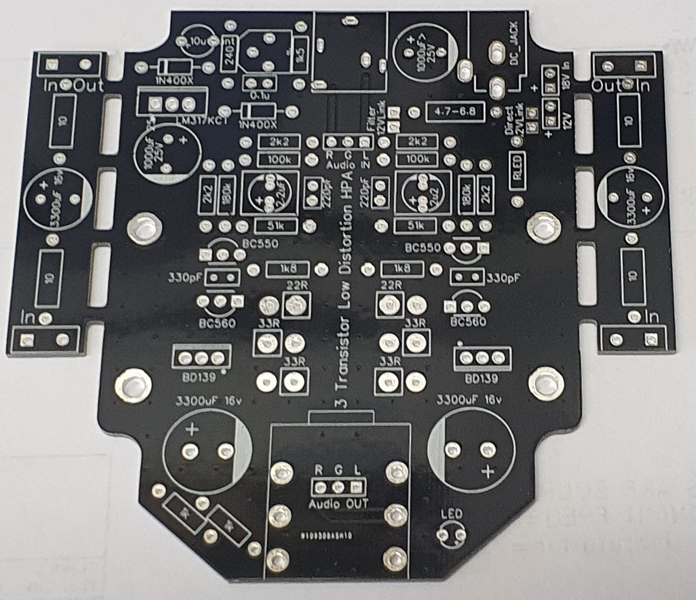
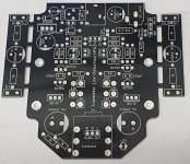
I couldn't resist making another layout for this one.
This time I wanted to make a board that would:
1. Be able to fit into a hammond 1455 series enclosure.
2. Also fit into the bud enclosures hh-3643.
3. Have options for direct 12v unfiltered or 12v CRC, or full LM317 19v.
4. Be able to be configured as a parallel amp.
So here we go:
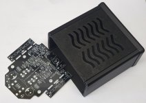
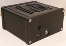
And a custom sized Hammond enclosure that I 3d printed:
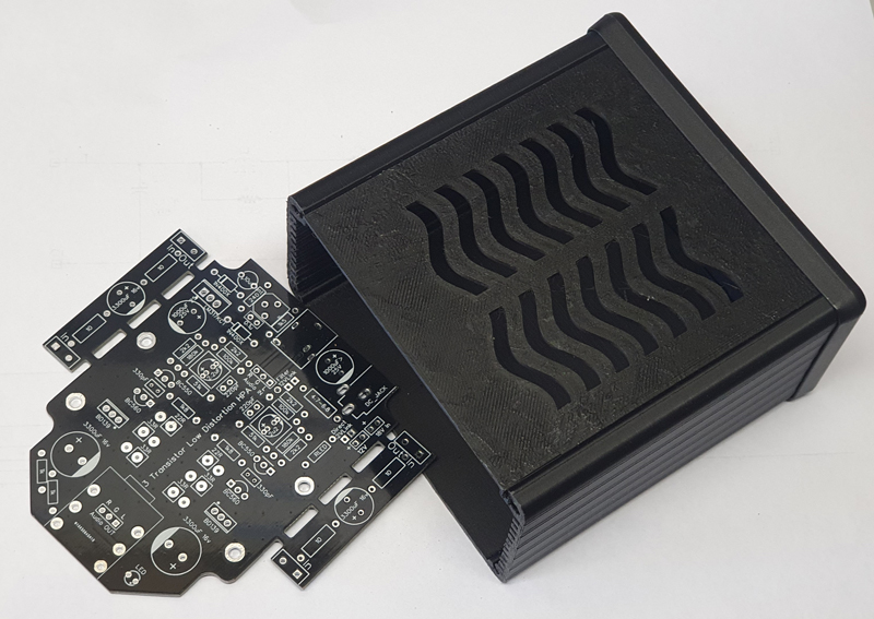
First test of the single board:

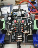
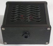
And in Parallel:

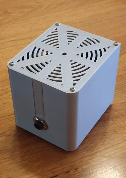
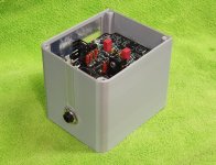
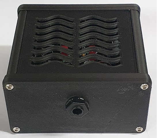
A custom enclosure for the parallel setup:
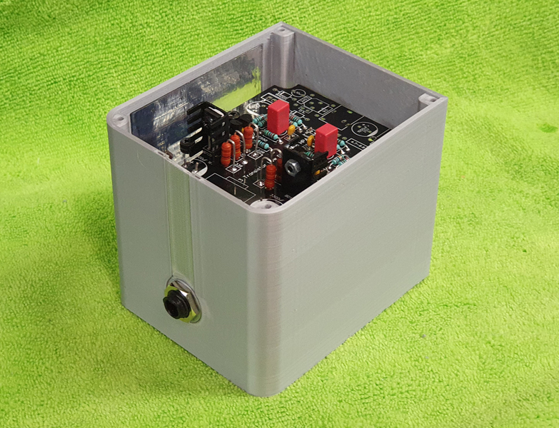
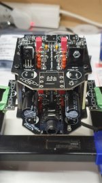
And the final close up of the parallel version:
**********************************************
Just some notes regarding the parallel layout.
I did make a mistake with the little parallel joining boards in that I had the balance resistors in the circuit before the output capacitors (hoping to save on capacitors). Unfortunately that means that any DC imbalance will cause reverse current to the weaker amp. It was hard to find any information on paralleling an AC coupled amp - the information that I could find was all centered around op amps. This error was easily rectified with some guidance from the good folk here on Diya and with a bit of creative component stuffing so all is good now!
There is a lot of negativity surrounding running parallel boards, so the main reasons I attempted this are:
1. I wanted to see how the amp measured with half the effective load.
2. I wanted to drive some inefficient Yamaha HP-50A(S) Orthodynamics.
3. As a learning experience and for more practice of the prototyping process.
4. Because it seemed like a cool project 😉
I'll post some measurements next.
I couldn't resist making another layout for this one.
This time I wanted to make a board that would:
1. Be able to fit into a hammond 1455 series enclosure.
2. Also fit into the bud enclosures hh-3643.
3. Have options for direct 12v unfiltered or 12v CRC, or full LM317 19v.
4. Be able to be configured as a parallel amp.
So here we go:
And a custom sized Hammond enclosure that I 3d printed:
First test of the single board:
And in Parallel:
A custom enclosure for the parallel setup:
And the final close up of the parallel version:
**********************************************
Just some notes regarding the parallel layout.
I did make a mistake with the little parallel joining boards in that I had the balance resistors in the circuit before the output capacitors (hoping to save on capacitors). Unfortunately that means that any DC imbalance will cause reverse current to the weaker amp. It was hard to find any information on paralleling an AC coupled amp - the information that I could find was all centered around op amps. This error was easily rectified with some guidance from the good folk here on Diya and with a bit of creative component stuffing so all is good now!
There is a lot of negativity surrounding running parallel boards, so the main reasons I attempted this are:
1. I wanted to see how the amp measured with half the effective load.
2. I wanted to drive some inefficient Yamaha HP-50A(S) Orthodynamics.
3. As a learning experience and for more practice of the prototyping process.
4. Because it seemed like a cool project 😉
I'll post some measurements next.
Attachments

Parallel amp measurements
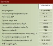
Here are the measurements, taken with a 245ohm load (same as all my previous measurements).
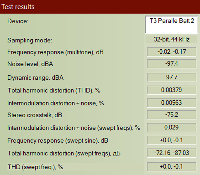
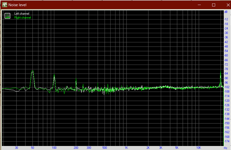
Noise floor centred around -102dB with a few peaks up to about -80dB. All inaudible.
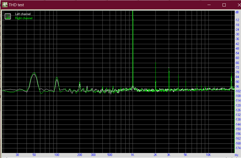
Distortion 0.00379%, one of my previous layouts was 0.00636%:
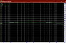
And a pretty flat frequency response, dropping just -0.3db between 5khz and 20khz:
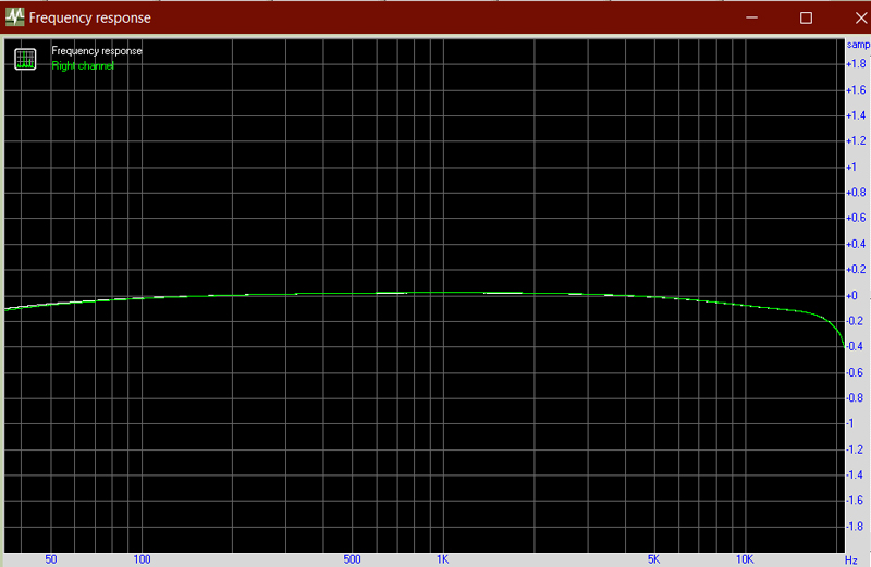
It sounds great and drives the Yamaha HP50 Orthodynamics with ease. It's the first time I have listened to those headphones and understood why people like them - previously they sounded muddy and not pleasant at all.
Ath-M50x sound excellent and I am yet to test the ESS-422h.
Here are the measurements, taken with a 245ohm load (same as all my previous measurements).
Noise floor centred around -102dB with a few peaks up to about -80dB. All inaudible.
Distortion 0.00379%, one of my previous layouts was 0.00636%:
And a pretty flat frequency response, dropping just -0.3db between 5khz and 20khz:
It sounds great and drives the Yamaha HP50 Orthodynamics with ease. It's the first time I have listened to those headphones and understood why people like them - previously they sounded muddy and not pleasant at all.
Ath-M50x sound excellent and I am yet to test the ESS-422h.
Attachments


I couldn't resist making another layout for this one.
Very, very cool project 😀
I couldn't resist making another layout for this one.
Wow, very impressive, congratulations!
DIY at its best! Very inspiring to see this combination of electronics, enclosure work/3D print.
Beautifully done Avtech23! I like the design, the dimensions of the enclosure, the way you parallelled the boards. Well done! 
And an interesting experiment. Apart from the measurements, compared to a single board, soundwise, do you hear a difference?
And an interesting experiment. Apart from the measurements, compared to a single board, soundwise, do you hear a difference?
Last edited:
Wow, avtech23! So much beautiful, hard work! I bet your 3-D printer sleeps well -- if you ever give it a night off! 😉

Last edited:
Thanks everyone,
I'm assembling a single board at the moment so that I can measure and listen to them in a more fair test.
Haha, no I don't let the 3d printer have much time to sleep - too many interesting projects to build!
I'm assembling a single board at the moment so that I can measure and listen to them in a more fair test.
Haha, no I don't let the 3d printer have much time to sleep - too many interesting projects to build!
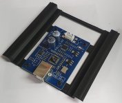
Here is the promised single board layout from the last batch of PCBs I had made.
I am using the 3D printed Hammond 1455 'style' case, modified to suit the board dimensions and with added top ventilation. (Hammond have 3D models available on their website, which is awesome for prototyping, but I will explicitly mention that I do buy genuine Hammond cases).
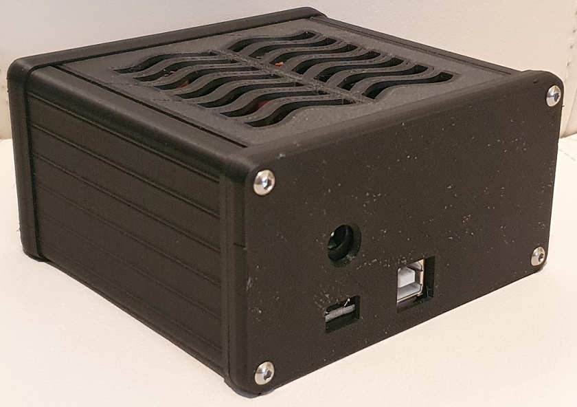
I am pairing this one with a $40 ebay SA9227/PCM5102A DAC module, which I have found to do a reasonable enough job for the price. I modified the DAC to use a JST and made a carrier for it.
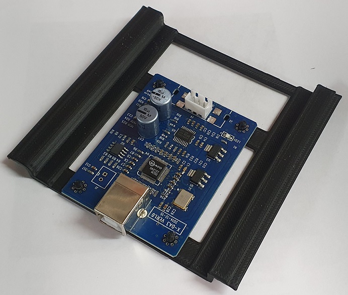
I can assemble the amp as a module using a JST-JST interconnect, then just slide it into place.
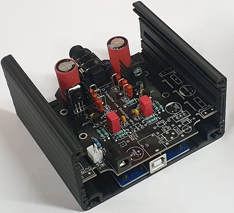
The board has some jumper pads to allow for different PSU filter configurations:
12v No Filter, 12v Reservoir Caps only, 12v in RC Only, 18v in LM317 Only, 18v in RC + LM317.
And this particular build has an optional 5v USB power supply (not shown). The 5v is raised to a usable level with an MT3608 boost converter and fed in to the 18v header. The little boost converter is mounted to the rear of the back cover and slots nicely between the DAC and AMP boards.
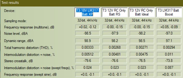
Headline THD between 0.00268-0.00333%, and noise towards the -100dB range depending on power supply and filter combinations.
I carried out some comparative measurements between different power supply and filter options, and shall present those in the next post.
I am using the 3D printed Hammond 1455 'style' case, modified to suit the board dimensions and with added top ventilation. (Hammond have 3D models available on their website, which is awesome for prototyping, but I will explicitly mention that I do buy genuine Hammond cases).
I am pairing this one with a $40 ebay SA9227/PCM5102A DAC module, which I have found to do a reasonable enough job for the price. I modified the DAC to use a JST and made a carrier for it.
I can assemble the amp as a module using a JST-JST interconnect, then just slide it into place.
The board has some jumper pads to allow for different PSU filter configurations:
12v No Filter, 12v Reservoir Caps only, 12v in RC Only, 18v in LM317 Only, 18v in RC + LM317.
And this particular build has an optional 5v USB power supply (not shown). The 5v is raised to a usable level with an MT3608 boost converter and fed in to the 18v header. The little boost converter is mounted to the rear of the back cover and slots nicely between the DAC and AMP boards.
Headline THD between 0.00268-0.00333%, and noise towards the -100dB range depending on power supply and filter combinations.
I carried out some comparative measurements between different power supply and filter options, and shall present those in the next post.
Attachments
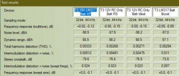

So here I tested out a few different power supply and filter options, primarily interested in the noise levels.
I had 4 different supply options: 2x 12v, 1x 18v and 1x 5v+boost converter.
The filter marked PoS in measurements is the 'PO89ZB' from here: https://www.diyaudio.com/forums/analog-line-level/354213-po89zb-inline-dc-filter-smps-wall-warts-preamps-hpa-korg-nutube-etc-new-post.html.
This filter is inserted as follows: PSU>>PO89ZB>>DC Jack>>Filter options>>VCC
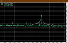
Power Supply: 'XP'.
This test is running 18V into the RC, then LM317 and dropping to exactly 12.00V. With / without PO89ZB filter at front.
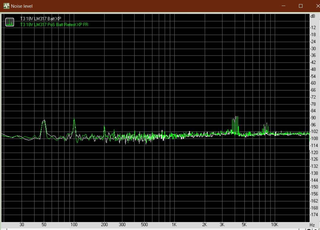
No appreciable difference between using the PO89ZB filter and without. Average noise levels are below -102dB and dead silent. THD 0.00333% (RC+LM317) and 0.00341% (PO89ZB+RC+LM317).

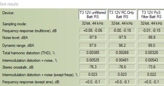
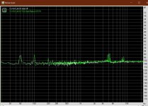
Power supply: 'RS'.
This particular power supply was from a NAS (Network Attached Storage) and seems to be filtered enough by itself to require no additional filtering for an inaudible noise floor, however benefits from a basic RC filter. Doesn't like the PO89ZB filter though.
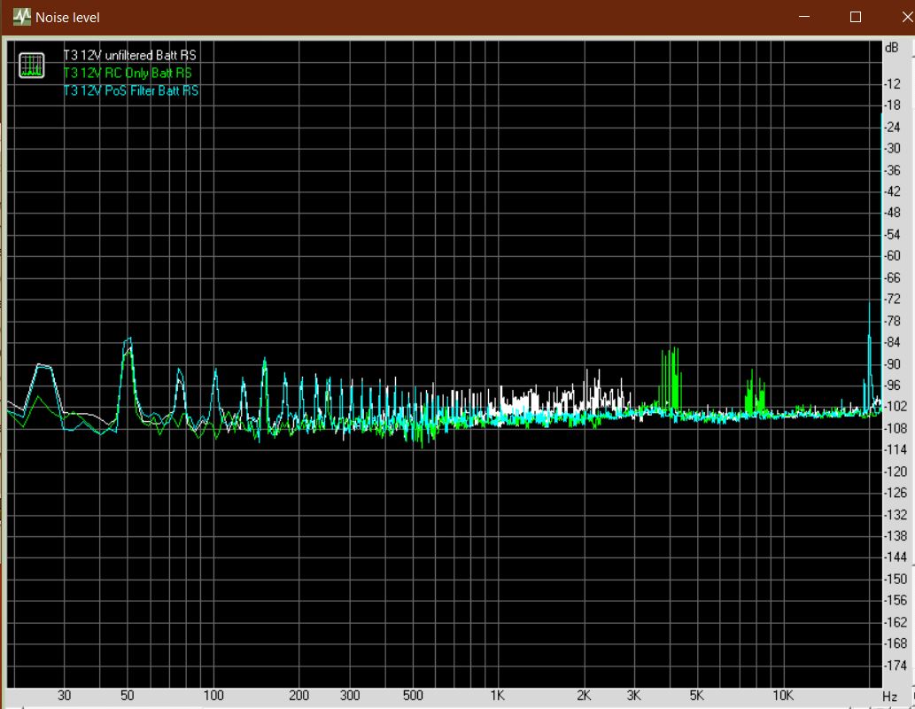
RC Only - good noise rejection -100dB below 3KHz but -85dB peeks at 4.1KHz and -93dB at 7.5KHz.
RC+PO89ZB - Multiple peaks around -91dB in lower range, that looks like ringing.
THD between 0.00268 (RC Only) and 0.00385 (RC+PO89ZB).
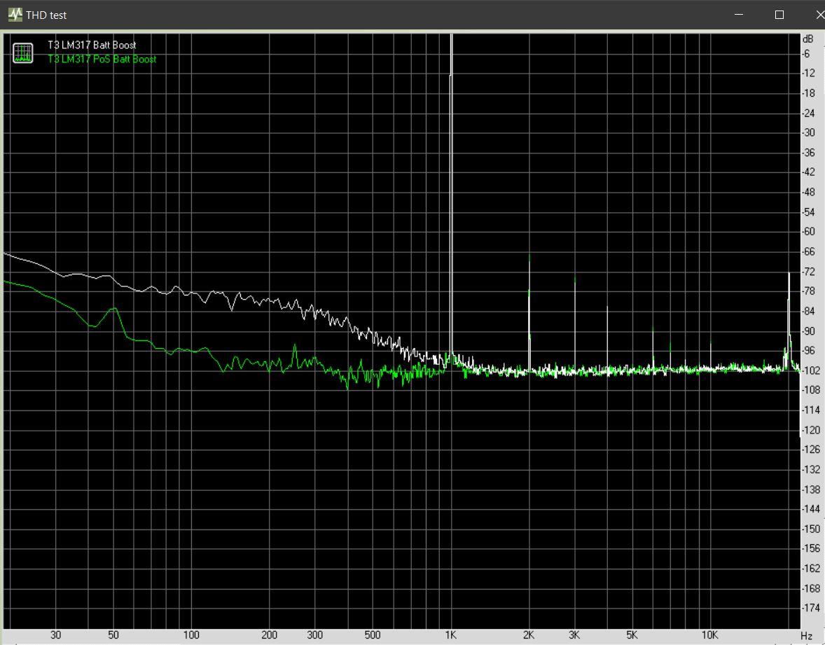
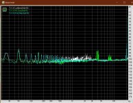
Power Supply: 'Ideal'.
So lets move to a pretty bad 'eBay/Ali special' brick SMPS.
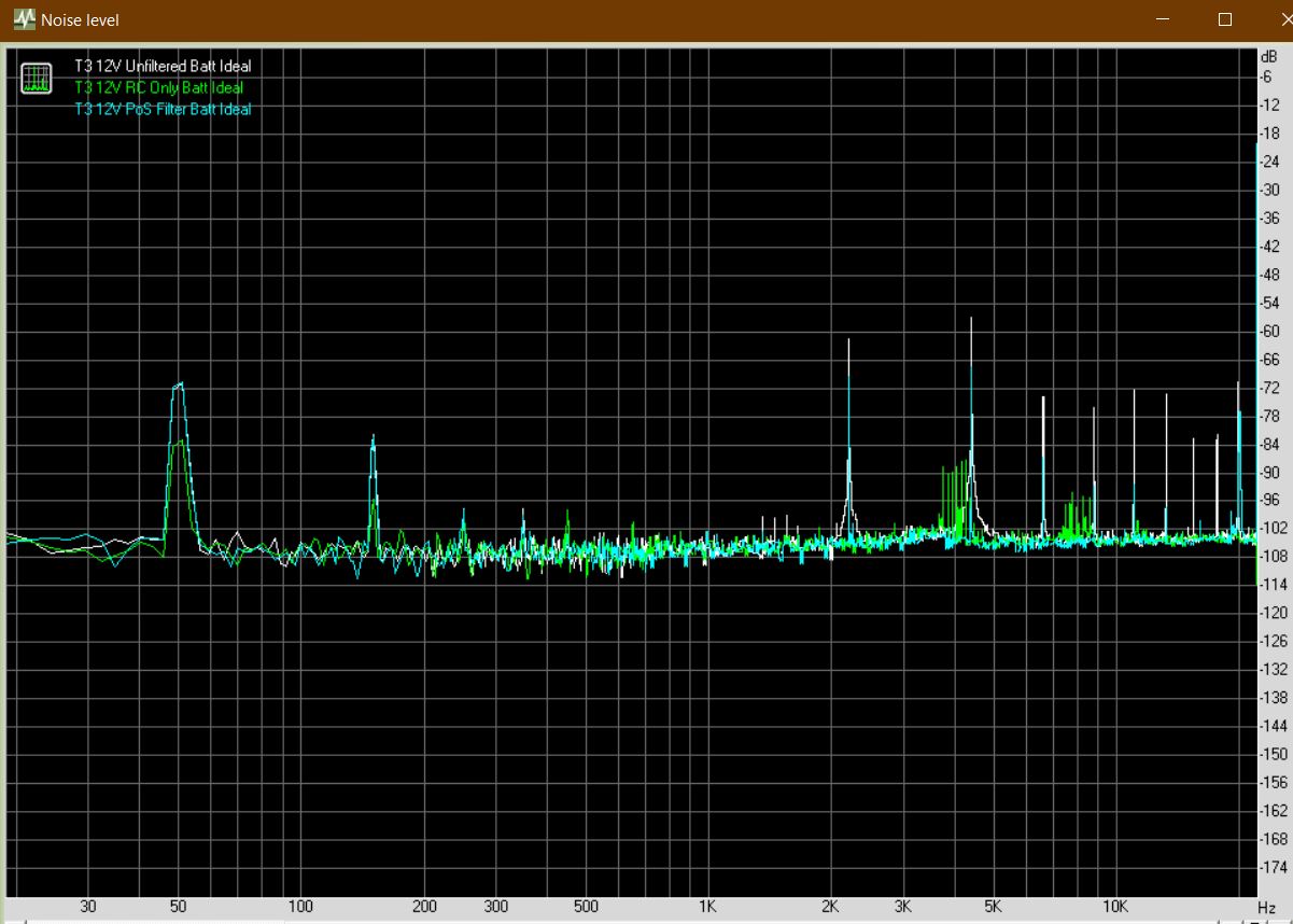
Unfiltered, this PSU is as expected - noisy! There is a -56dB spike centered around 4.4khz and -62dB around 2.2khz.
PO89ZB filter Only - doesn't attenuate the 2.2k and 4.4K peaks enough, with noise still there at -68dB.
RC on it's own is enough to tame the noise with 100hz spaced peaks at just above -84dB.
Here is a close up of the 4.4khz noise:
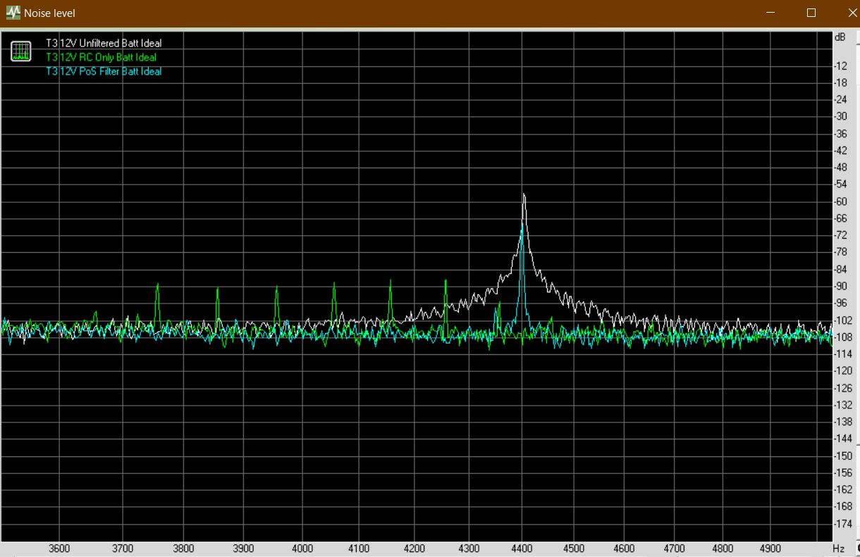
The RC-only filter was enough to make the noise inaudible.
THD between 0.00271% (RC) and 0.00420% (RC+PO89ZB).
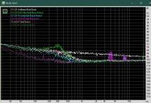
Power supply: 'Boost'.
Finally, let's make the power supply really noisy. Here we use a 5v phone charger and put it into a very cheap MT3608 DC-DC Boost converter to lift the voltage.
Each time, the voltage at the VCC rails is set to 12v (either boosted to 12v, or to ~18v and dropped back down by the LM317).
Unfiltered - as expected, has a horrible low frequency hash and white noise that is quite obtrusive. THD was 1.858%. 😱
RC Only and RC+LM317 were not able to reduce the noise below 1khz to an acceptable level. THD 0.00288 and 0.00294 respectively.
PO89ZB only - Had a bad peak at 300Hz, but quieter above 1kHz. THD of 0.00286.
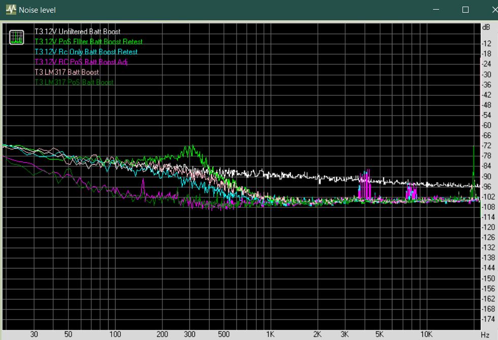
Here is a comparison between LM317 with and without the PO89ZB filter:
Best results were from RC+PO89ZB and LM317+PO89ZB filter - the PO89ZB filter really makes a difference here in terms of noise, but increases distortion with THD of 0.00301% and 0.00380% respectively.
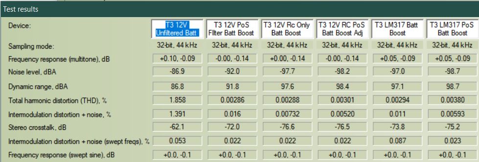
The amp is quiet enough to acceptably use a 5v with just the RC+LM317 filter, however a nicely filtered 12v or voltage stabilised 18v is always going to be preferred.
I had 4 different supply options: 2x 12v, 1x 18v and 1x 5v+boost converter.
The filter marked PoS in measurements is the 'PO89ZB' from here: https://www.diyaudio.com/forums/analog-line-level/354213-po89zb-inline-dc-filter-smps-wall-warts-preamps-hpa-korg-nutube-etc-new-post.html.
This filter is inserted as follows: PSU>>PO89ZB>>DC Jack>>Filter options>>VCC
Power Supply: 'XP'.
This test is running 18V into the RC, then LM317 and dropping to exactly 12.00V. With / without PO89ZB filter at front.
No appreciable difference between using the PO89ZB filter and without. Average noise levels are below -102dB and dead silent. THD 0.00333% (RC+LM317) and 0.00341% (PO89ZB+RC+LM317).
Power supply: 'RS'.
This particular power supply was from a NAS (Network Attached Storage) and seems to be filtered enough by itself to require no additional filtering for an inaudible noise floor, however benefits from a basic RC filter. Doesn't like the PO89ZB filter though.
RC Only - good noise rejection -100dB below 3KHz but -85dB peeks at 4.1KHz and -93dB at 7.5KHz.
RC+PO89ZB - Multiple peaks around -91dB in lower range, that looks like ringing.
THD between 0.00268 (RC Only) and 0.00385 (RC+PO89ZB).
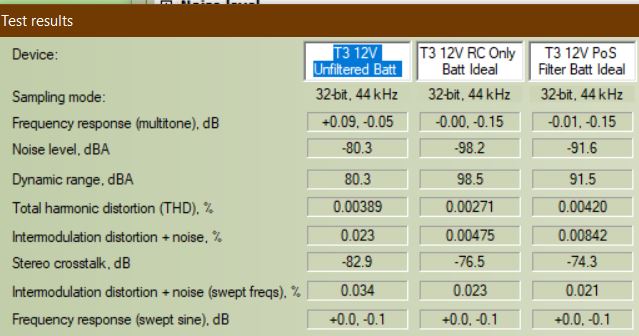
Power Supply: 'Ideal'.
So lets move to a pretty bad 'eBay/Ali special' brick SMPS.
Unfiltered, this PSU is as expected - noisy! There is a -56dB spike centered around 4.4khz and -62dB around 2.2khz.
PO89ZB filter Only - doesn't attenuate the 2.2k and 4.4K peaks enough, with noise still there at -68dB.
RC on it's own is enough to tame the noise with 100hz spaced peaks at just above -84dB.
Here is a close up of the 4.4khz noise:
The RC-only filter was enough to make the noise inaudible.
THD between 0.00271% (RC) and 0.00420% (RC+PO89ZB).
Power supply: 'Boost'.
Finally, let's make the power supply really noisy. Here we use a 5v phone charger and put it into a very cheap MT3608 DC-DC Boost converter to lift the voltage.
Each time, the voltage at the VCC rails is set to 12v (either boosted to 12v, or to ~18v and dropped back down by the LM317).
Unfiltered - as expected, has a horrible low frequency hash and white noise that is quite obtrusive. THD was 1.858%. 😱
RC Only and RC+LM317 were not able to reduce the noise below 1khz to an acceptable level. THD 0.00288 and 0.00294 respectively.
PO89ZB only - Had a bad peak at 300Hz, but quieter above 1kHz. THD of 0.00286.
Here is a comparison between LM317 with and without the PO89ZB filter:
Best results were from RC+PO89ZB and LM317+PO89ZB filter - the PO89ZB filter really makes a difference here in terms of noise, but increases distortion with THD of 0.00301% and 0.00380% respectively.
The amp is quiet enough to acceptably use a 5v with just the RC+LM317 filter, however a nicely filtered 12v or voltage stabilised 18v is always going to be preferred.
Attachments
-
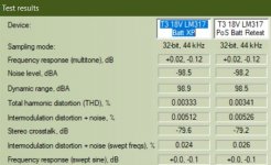 table xp.JPG36.9 KB · Views: 731
 -
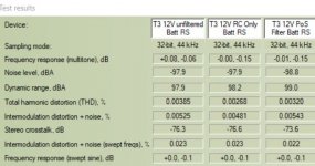 table rs.JPG43.4 KB · Views: 729
 -
 table ideal.JPG48.2 KB · Views: 732
 -
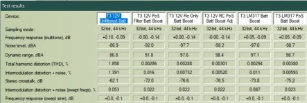 Table boost.JPG73.4 KB · Views: 737
 -
 noise4k4 ideal.JPG152 KB · Views: 720
 -
 Noise xp.JPG133.7 KB · Views: 1,493
 -
 Noise RS.JPG138.1 KB · Views: 730
 -
 noise ideal.JPG160.3 KB · Views: 727
 -
 Noise boost.JPG129.4 KB · Views: 721
 -
 THD LM vs PoS.JPG156 KB · Views: 733
You put a lot of work into that Avtech23! Very interesting to see the differences of good and bad power supplies in these measurements.
Without much doubt this is audible, especially when using the cheapest one like you mentioned.
I have no room for test equipment so I must rely on helpful people like you and my ears. Thanks!
Without much doubt this is audible, especially when using the cheapest one like you mentioned.
I have no room for test equipment so I must rely on helpful people like you and my ears. Thanks!
Zobel network
A Zobel network seems to be used as a precautionary measure although this amplifier may be robust enough not to need it. However, I added it as an experiment. Having headphones it may be more easy to hear a difference with or without, if any.
It did not get worse, still sounds fantastic but it is possible a improvement or regression is below my hearing threshold. I have no equipment to test it, but I incline it to be a slight improvement although I may be fooling myself.
The Zobel network consists of a resistor of 100 ohms and a capacitor of 100nF in series at the output to ground. I calculated it using Zobel-Glied-Rechner | Boucherot-Schaltung | Jobst-Audio - Tontechnik. The inductance of my Beyerdynamics DT770 80 ohm headphone driver is a wild guess, 1 mH.
Any opinion on using a Zobel network?
Last edited:
Did a V1.1 of my PCB. Suggestions and criticisms always welcome 🙂
Can you also present the wiring diagram?
I'm interested in how the relay is connected.
Thanks.
- Home
- Amplifiers
- Headphone Systems
- 3 Transistor HP Amplifier with low dist