I couldn't find a 'maida LT3091' as an implementation for a negative rail - anyone tried/has one?
I'm using a 'standard' Maida for a B- (-300VDC) supply, just connected the positive output to ground and used ground as the negative supply. It works perfectly.
I also have some bipolar maida PCBs in my spares stash, purchased from a chap on Swap Meet - I can spare one or two if of interest?
I'm using a 'standard' Maida for a B- (-300VDC) supply, just connected the positive output to ground and used ground as the negative supply. It works perfectly.
I also have some bipolar maida PCBs in my spares stash, purchased from a chap on Swap Meet - I can spare one or two if of interest?
So that's the same as Jan's with two isolated secondaries and two fb rect bridges. I was under the impression that running a -320 to 320 causes issues with the transformers loading etc.
Last edited:
So that's the same as Jan's with two isolated secondaries and two fb rect bridges.
That works with the 21st Century Maida Regulator as well. As long as you have two separate secondaries - one for the positive supply and another for the negative supply - it'll work just fine.
Tom
So that's the same as Jan's with two isolated secondaries and two fb rect bridges.
Yes, essentially the bipolar units are two seperate maida regulators so each has its own transformer or secondary.
Could I use the Maida for the B+ of a pair of Korg Nutubes? Each nutube needs 75V and will draw 64uA, for a total of 128uA (or 0.128mA).
I've attached the calculator output. For R3 and R9, I was planning on using 1W Vishay CMF60 resistors. Are those alright?
I've attached the calculator output. For R3 and R9, I was planning on using 1W Vishay CMF60 resistors. Are those alright?
Attachments
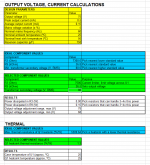
Don't forget to account for the load current in that case. I'd probably make R3 = 100 Ω. That'll set the current limit to about 35 mA, which would be plenty.
1 W resistors would be plenty.
A use case where hardly any current would be drawn from the regulator did not occur to me when I wrote the spreadsheet, so I didn't account for that. You'll always have at least 2 mA flowing through R3 due to the feedback resistors, so it really should be no higher than 1.6 kΩ.
Tom
Last edited:
Don't forget to account for the load current in that case. I'd probably make R3 = 100 Ω. That'll set the current limit to about 35 mA, which would be plenty.
1 W resistors would be plenty.
A use case where hardly any current would be drawn from the regulator did not occur to me when I wrote the spreadsheet, so I didn't account for that. You'll always have at least 2 mA flowing through R3 due to the feedback resistors, so it really should be no higher than 1.6 kΩ.
Tom
Hi Tom, what is the psrr of the reg, I can't find the graph..?
100-ish dB at mains frequency if I recall correctly. It depends some on the output voltage. I'd have to rerun some simulations to check. Which output voltage are you looking for?
Tom
Tom
100-ish dB at mains frequency if I recall correctly. It depends some on the output voltage. I'd have to rerun some simulations to check. Which output voltage are you looking for?
Tom
Whatever voltage... is there a simulation file in the thread?
@bogdan
ADI/Linear also have a reference example when you open the device
Thanks a lot jackinnj.
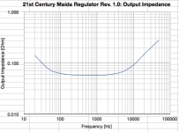
Only a simulation, set up to measure the output impedance. If you change the right axis to "phase delay", the "Q" of the circuit at the impedance peak is frequency * phase delay * pi.
Nothing beats putting it on the bench and measuring impedance vs frequency/
Nothing beats putting it on the bench and measuring impedance vs frequency/
Whatever voltage... is there a simulation file in the thread?
I doubt it. There is a schematic in Post #1, though.
I've made a few tweaks since then, but it should provide a starting point for you if you'd like to DIY the circuit.
Tom
I doubt it. There is a schematic in Post #1, though.
I've made a few tweaks since then, but it should provide a starting point for you if you'd like to DIY the circuit.
Tom
It's ok, thanks, jackinnj sent simulation file, I need it only for comparation, I'm experimenting with another "maida type" topology... Btw I'm used to Micro Cap, LT spice is still not user friendly after all these years. 😡
Yeah. I'm not a fan of LT Spice either. It reminds me of software from the late 1980s or early 1990s.
Tom
Tom
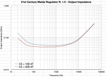
anyone else running the simulation with LTSpice -- use {X} for the ESR of C2 and the following parameter step instruction: .step param X list 100u 10m 500m
QQ- what ripple input would expect for a tube amp? I’m targetting as close to sub 0.1uV ripple (320V 160-200mA)
Do users normally use one or more chokes to give a starting point for the regulator to work from at that level of output? (A 3H choke with 375uF caps give ~ -53dB for example)
Do users normally use one or more chokes to give a starting point for the regulator to work from at that level of output? (A 3H choke with 375uF caps give ~ -53dB for example)
- Home
- Vendor's Bazaar
- 21st Century Maida Regulator