Got my Maida in use and it works great, but I'm worried that I ordered too high voltage of a transformer. The voltage at my bridge rectifier is about 390V, and I only need the Maida to be 300V. The heatsink gets to about 115 degrees F, as it's probably 7-8 watts (75V drop at about 100mA). Replacing the transformer isn't really an option, but could I put a high-wattage resistor after the bridge rectifier?
Upon further measuring, I think it's closer to 60 C (which is what the spreadsheet calculates). Well within the 150 C limit of the STW11NK90Z I guess, so it should be ok
Technically the 150 ºC limit is the junction temperature. I forget what the thermal resistance is for the TO-247 package, but that and the thermal pad probably add up to ~1.5-2K/W, so figure the junction is 70-75 ºC if the heat sink reaches 60 ºC. Thats' very comfortable.
Tom
Tom
Hi Tom,
i was lurking for your reg for a longer time now.. Two things - are you planning a higher voltage version (up to 1250V would be nice)?
And as i usually make my own pcb with various functions on it (delay's and so on), is there way to buy only the schematic from you so i could implement it into a pcb wich fits one of my personal builds?
Ensuring that the MOSFET survives startup at 1250 V would be a significant challenge. I suppose you could use many in parallel...
I have no plans for going that high in voltage.
The most recent schematic for the Maida Reg. is in the design doc, which you get when you buy the board. If you aren't going to use the board, I can certainly sell the design doc. Just contact me by email (add @neurochrome.com to my user ID here). In addition to the schematic, the design doc includes all the information needed to get the circuit running well and a few pointers on what to watch out for in the design. It also includes a calculator spreadsheet so you can determine the couple of components that are customized to your build as well as the size of the heat sink.
Tom
Two things - are you planning a higher voltage version (up to 1250V would be nice)?
We all know about the mirrors of the Hubble Telescope -- what we haven't heard a lot about are NASA's mistakes on the 1.5kV power supply PCB's -- bad layout, bad trace spacing, bad dielectric...
Yep. "Fun" stuff happens at high voltage - especially in the vacuum of space. Beware that resistors have a max. voltage spec too.
Tom
Tom
Okay cool! Will contact you by mail! No worries to the others - since more than 15 years i made several experiments in the killervolt region (including 8kV / 1A primary cirquit for a tesla coil). Only point is, that i mostly use obsolete gear like tubes for it wich is way over engineered for this purpose.. 🙂 distance matters!
I'm contemplating building this regulator for my El Cheapo-ish build (~80-100mA, 360V). I think I've read this thread three times and I'm learning by reading and simulating in ltspice.
I was wondering... Around post #150 a sub-thread started with alternative values for the divider resistors (R4569) and a bit later a low current zener was introduced. Looking at the photos on the neurochrome website, it seems that R1+R10 and D2 is the low current variant, but the proposed resistor values all were positive about seem to have not made it to v2.12. What is the reasoning behind that?
Also, I'm having troubles finding a model for the low current variant for D2. I would like to see for myself what is the best combination of R1 and R10 is and try to understand why the optimum is where is it.
Thanks for this nice thread and continuous involvement of you, Tom.
I seem so recall looking at those resistors eight years ago when that idea first surfaced. There was some issue with that idea, but I don't recall specifically what it was. One drawback of raising the reference voltage is that the regulator will need more headroom.
I don't use a low-current model for D2 in my sims. It works fine as long as you give the regulator enough headroom in simulation.
Tom
I don't use a low-current model for D2 in my sims. It works fine as long as you give the regulator enough headroom in simulation.
Tom
Hey Tom, I have a couple questions for you:
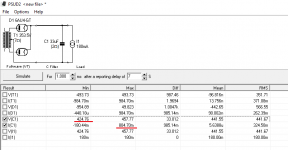
1. In your calculator, I set the output voltage to 365V, average current at 180mA, and 33uF input capacitor. The calculator recommends a PT with a secondary of 362V. In PSUD, I modeled a PSU with a 350V secondary, a 180mA load, and tube rectifier... and after the first cap (input to the maida regulator), I see a minimum of 424V. That's way beyond the needed 15V drop that the regulator needs for a desired voltage of 365V. Could I possibly use a PT with a lower secondary than the calculator's recommendation, say 350V instead of 362V? Or am I not modeling it in PSUD correctly?
2. How do I see peak output current from PSUD? Is it the peaks in the graph after the inrush current has calmed down? In this case, about 804mA according to PSUD? That seems really high to me. I'm looking at the current in the capacitor before the regulator.
Thanks!
Carl
Attachments
My calculator spreadsheet assumes you'll be using a solid state rectifier (basically zero voltage drop).
As for the output current keep in mind that the conduction angle of the rectifier is relatively small, so the rectifiers will have to replenish the charge in the supply cap in a small fraction of the mains period. That's why you see the high ripple current. That's inconsequential for the Maida Regulator as it'll be on the load side of the cap.
Tom
Thanks for the response. What I was saying is even with the tube rectifier V drop and a transformer with a 350V secondary (which was lower than the calculator's 362V recommended), the input voltage to the regulator was still adequate, with about 60V of headroom above my target voltage. In other words, it seems like the calculator aims really high for input voltage.
Suppose I use a solid state rectifier instead. My question still stands: can I use a transformer with less than the calculator's recommended secondary voltage if PSUD reports that I'll have more than 15V headroom for the regulator? For example, in my same setup in PSUD I changed the rectifier to SS and used the 362V secondary the calculator recommends. The resulting input voltage to the regulator is 475V, which is a full 110V over what my target output voltage is. That's way more than the needed 15V headroom.
I'm not sure I understand the part about peak output current. I'm just trying to find what value I should put as peak output current in the calculator. I assume that the 180mA load I specified is the average output current. But I'm not sure about peak current.
I appreciate the help.
I don't have the math of the spreadsheet committed to memory, but I would think that any difference between PSUD-II and the spreadsheet would be due to differences in mains frequency, mains variation, and peak load current.
I would expect the results from PSUD-II to be closer to reality than the results from my spreadsheet. I would think that the two would agree within, say, a few percent -- assuming that you use the same inputs (mains variation, mains frequency, etc.). That said, my spreadsheet uses some approximations. It's an Excel sheet, not a circuit simulator.
You're seeing a difference beyond a few percent, so I would try rerunning the PSUD-II sim at low mains and with the peak current instead of the average current.
The average current should be set to whatever your circuit uses at idle (or with an average signal). The peak current should be set to whatever your circuit uses when it delivers the maximum signal.
Take my DG300B for example: At idle a stereo DG300B uses about 200 mA (12 mA for the input tube, 5 mA for the driver, 85 mA for the 300B, per channel -> I_avg = 2*(12+5+85) = 204 mA give/take. The driver and input tubes are CCS loaded, so their current draw won't change versus signal level, but the output tube's current draw will. It could change by as much as 85 mA, so I_peak = 2*(12+5+2*85) = 374 mA. I designed the regulator for 400 mA.
Your circuit is different and you'll have to work out those values. You can do so either by simulating the circuit, by reading the tube data sheets and working out the load lines, or by asking the designer of the circuit.
Tom
BTW: Going with a solid state rectifier allows you to increase the supply capacitance before the Maida Regulator. That gives you lower ripple voltage, which makes life easier both for the mains transformer and the Maida Regulator.
Tom
Tom
I couldn't find a 'maida LT3091' as an implementation for a negative rail - anyone tried/has one?
From other posts in this thread I gather there isn't such a thing. I needed some -150V regulators and went with the 20th century Maida.
I couldn't find a 'maida LT3091' as an implementation for a negative rail - anyone tried/has one?
LT3091 as control element. You will have to redesign Tom's PCB, however!
- Home
- Vendor's Bazaar
- 21st Century Maida Regulator