I think you mixed up uV and mV. Assuming you meant uV, it is all consistent with a very low resistance on-chip grid and the usual thin bondwires. Either the side contacts are double-bonded while top and bottom are not, or the top and bottom wires are much longer than the side contacts.
Buffers and dividers mainly (though not exclusively) affect the phase noise floor, while Andreas mainly cares about close-in phase noise.
Not so for sine/square converters, for the very same reason I mentioned above; the resulting square wave rise/fall time significantly affects the phase noise. You can do the math, get a phase modulated sine and calculate the convolution with variable, finite, rise/fall time pulses of T/2 width, where 1/T is the input PM signal fundamental frequency, and note the effect on the output signal phase modulation.
About the close-in phase noise, this is a second contention point. We should be much more concerned about the effect of the moon phase on the SQ, a DAC is not a missile guidance system or a phase array radar.
P.S. You can find almost all the tedious math done in this PPT https://www.google.com/url?sa=t&rct...distr=Public&usg=AOvVaw3KCKr2iBFTaE4vu9iDMdZ7
Last edited:
I don't get your point about rise and fall times and close-in phase noise. When a square wave is randomly but slowly modulated in time, all harmonics get phase modulated and you get sidebands around each and every harmonic. A given time error is a larger percentage of the period time for the higher harmonics, so the higher harmonics get phase modulated more strongly than the low harmonics. For close-in noise, none of that affects the phase noise around the fundamental. It's different for wideband phase noise, as the spectra around the harmonics then overlap, so you get folding effects.
I agree with you that close-in phase noise can't be as important as Andreas thinks it is. It produces skirts around the spectral peaks of the signal that ideally shouldn't be produced, but even with the cheapest crystal oscillator, those skirts are completely negligible compared to what you get from the wow and flutter of the very best professional analogue tape recorder ever made. Still, if people are having fun minimizing those skirts, let them minimize them. At least it won't do any harm.
I agree with you that close-in phase noise can't be as important as Andreas thinks it is. It produces skirts around the spectral peaks of the signal that ideally shouldn't be produced, but even with the cheapest crystal oscillator, those skirts are completely negligible compared to what you get from the wow and flutter of the very best professional analogue tape recorder ever made. Still, if people are having fun minimizing those skirts, let them minimize them. At least it won't do any harm.
I think you mixed up uV and mV. Assuming you meant uV, it is all consistent with a very low resistance on-chip grid and the usual thin bondwires. Either the side contacts are double-bonded while top and bottom are not, or the top and bottom wires are much longer than the side contacts.
Oh crap you're right it's µV, thanks 😀
I wrote mV by mistake. So still 0.1-0.25 ohm.
Still, if people are having fun minimizing those skirts, let them minimize them. At least it won't do any harm.
Regarding phase noise and rise/fall times, check this one: https://authors.library.caltech.edu/4917/1/HAJieeejssc98.pdf Remember, we are talking fs jitter, not ps or more.
What I find infuriating is the propaganda machine that is perpetrated around this close-in phase noise concept, by the usual suspects, and the amount of pataphysics it is wrapped into. All perpetrated only to persuade the innocents to part from their hard earned money, effectively selling an illusion of SQ. When the money could be spent on things that really matter for SQ, like speakers, room acoustics, perhaps a better amplifier, etc...
Thanks, I didn't know the famous Hajimiri paper was freely accessible. In any case, it relates to what happens inside the oscillator, not to a sine-to-square converter after the oscillator. It's the accumulating effect of phase disturbances (a free-running oscillator never recovers from a phase disturbance) that causes white noise around oscillator harmonics to be converted to -20 dB/decade close-in phase noise. A sine-to-square converter after the oscillator in principle doesn't inject any noise into the oscillator that can lead to phase errors that get accumulated. A possible exception is the base current shot noise of a bipolar sine-to-square converter connected straight to the tank.
Some more material:
http://smirc.stanford.edu/papers/CICC99p-tom.pdf
Sci-Hub | The design of low jitter hard limiters. IEEE Transactions on Communications, 44(5), 601–608 | 10.1109/26.494304
https://people.mpi-inf.mpg.de/~adogan/pubs/IFCS2019_collins_isf.pdf
[time-nuts] Understanding Oliver Collins Paper "Design of Low Jitter Hard Limiters"
That should make it clear enough, that the input filter of the timepod does
not throw away valuable information, it does throw away unwanted dirt,
contrarily to what Ian claims in the other thread.
The zero crossing of the fundamental is all that counts.
Cheers, Gerhard
Last edited:
Extrapolating microwave circuitry behavior to audio DAC frequencies, nice try. Why don't you just match all clock lines and be done with it. Hint, it is not needed since the clock trace lengths are always (except pathological implementations) much, much shorter than the clock wave length/16. Extreme example: 100MHz clock, assume x10 to provide good bandwidth, 1GHz has 30cm wave length, any PCB trace running an 100MHz clock under 2cm will exhibit very weak transmission line characteristics.
Attachments
I am definitely not an expert in this area, but it appears to me the Collins paper disagrees (my comments in []).
The examples in Section I as well as certain precise tracking applications [3] demand a 10 ns RMS jitter [which is 6 orders of manitude compared to what is discussed here]. Unfortunately, a slope gain of 10^6 is required to bring the 1 V/S signal up to digital logic speeds, and, if all of this gain were incorporated into a single stage [which is what the sine/square under discussion is] with the above parameters, it would produce a jitter orders of magnitude too large. Very careful custom design of the stage amplifier could lower the noise spectral density by 6-9 dB; however, the required jitter could never be achieved in a single stage of slope amplification without a major breakthrough in semiconductor devices. The amplification must, therefore, be performed in stages as described in the next section [which is not the case here]
Can't quote anything from Markw4's post, but I can ask: So what? Did the topic change to radar technology?
Syn08, I think You are brutally off-pist, what regards the Collins paper. The citation talks about a ZeroCrossDetector, as in a DMTD setup, after the mixer stages, squaring up the beat frequency signal, which is Herz frequency range. They talk about 1V/s slew rate!!
It all has totally nothing to do with our topic here, squaring up 10/20MHz sine signals..
The methods, the points taken in that paper could be partially valid, I think that's why Gerhard cited it.
It all has totally nothing to do with our topic here, squaring up 10/20MHz sine signals..
The methods, the points taken in that paper could be partially valid, I think that's why Gerhard cited it.
Post with no text
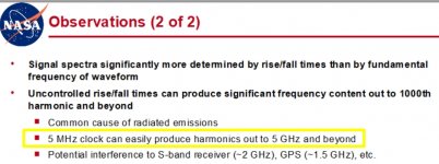
Yes, can, in a setup with the craziest edge rates and no standard mitigations. Plus, the quote disregards magnitude. I'd love to know how many products have you seen through EMC testing and how many showed significant ~5 GHz emissions from an LVCMOS clock? I know what I've seen.
Overall, just another bogeyman to point to. I'm not sure why you're worried about behavior at the extremes when you're still working with eval boards with fundamentally flawed layouts that can't be fixed... which then end up further butchered with "mods" and connected to a bunch of off-the-shelf PCBs (including clocks) cobbled together.
Last edited:
Syn08, I think You are brutally off-pist, what regards the Collins paper. The citation talks about a ZeroCrossDetector, as in a DMTD setup, after the mixer stages, squaring up the beat frequency signal, which is Herz frequency range. They talk about 1V/s slew rate!!
It all has totally nothing to do with our topic here, squaring up 10/20MHz sine signals..
The methods, the points taken in that paper could be partially valid, I think that's why Gerhard cited it.
Guys, you have to decide what you are talking about. Gerhard says “it’s all about zero crossing” now you jump in and say zero cross detection is irrelevant in this discussion. Once again, for anybody looking forward for a direct proof, it is sufficient to consider a PM sine (or PM + AM) and calculate the convolution with a trapezoidal waveform, followed by noise integration. It is brutal, but doable. Intuitively, you may think on how a signal gain can be graphically estimated, by projecting the input signal on the amplifier Gm characteristic (which is the “trapeze”, the higher the slope, the higher the gain). This is just an intuitive view because, as Collins mentions, the noise gets processed only as long as the “trapeze” doesn’t saturate, at those points the gain drops to zero, while an infinite raising “trapeze” is not a realistic case. Now, if a LPF is placed after the limiter, the signal is back to the initial, since all (amplified) harmonics are gone, so jitter would be the same. In the real case, as Collins shows, a RC cell as a LPF is not good enough, the jitter could still be much larger than the original.
A good DIY partner would of course realize that the Collins ISF formalism presented in his classic paper is by no means limited to one application, it is general.
P.S. I’ll try to do the math myself, and try to build a behavioural synthetic simulation (hopefully it’s possible in PSpice), but it will take time, and my time budget for DIY is tight, too many projects are ongoing. Until I’ll have some relevant results to show, I’ll stop here, this is obviously not the right forum to discuss such abstract topics.
Meantime, I’m looking forward for listening impressions of an oscillator with -130dB close-in phase noise, and suspended in rubber strands
 . I know, “I understand **** of what you guys are babbling, but I know what I hear, and I trust my ears”.
Last edited:
The "small" difference between the Collins and 'our' application that as pointed out by him, he has to apply 10^6 gain, while in our case gain of 6 is more than sufficient, for a 20MHz signal..
It's all completely off topic, but are you all writing about the phase noise floor or about close-in phase noise? I've only browsed through his paper, but at first sight Collins doesn't write anything about close-in phase noise.
Yes, can, in a setup with the craziest edge rates and no standard mitigations...
Personally, I worry when I see too many people doing things like:
https://www.diyaudio.com/forums/dig...mate-weapon-fight-jitter-657.html#post6668751
The latest add-on for that is a reclocker board (fed by RPi GPIO bus style interconnects) that aims to produce the squarest of fast rise time square waves the designer can figure out how to make.
I have have repeatedly tried to point out that using the fastest possible rise times doesn't always make dacs sound their best. Apparently no one cares enough to do an experiment to find out though.
By the way, looks like your conspiracy theory pal must be in the business of fixing up rooms and selling speakers, since that is what he recently promoted. Yes, it all makes perfect sense now


Last edited:
Buffers and dividers mainly (though not exclusively) affect the phase noise floor, while Andreas mainly cares about close-in phase noise.
Close in noise is part of the floor, just a little piece in the corner 🙂
//
hm.. with the difference that you can not change that lower part so easily.
while the flat part picks up a lot of influence, logic gate speed, noise, power supply ground loops etc. Most if it gets in as extra spuries frequencies.
while the 1/fxx part is primarily defined by crystal, and partly by oscillator.
Ciao,
while the flat part picks up a lot of influence, logic gate speed, noise, power supply ground loops etc. Most if it gets in as extra spuries frequencies.
while the 1/fxx part is primarily defined by crystal, and partly by oscillator.
Ciao,
They may give it a try if you reveal the details of your experiment setup.Apparently no one cares enough to do an experiment to find out though.
Someone recently said, "First attempt at a fix should probably be to try moving the sub around the room to see if that helps. Using stereo subs can sometimes help too. If those things don't work, then construction of a bass trap may correct the problem better than a notch filter."By the way, looks like your conspiracy theory pal must be in the business of fixing up rooms and selling speakers, since that is what he recently promoted. Yes, it all makes perfect sense now
By the way, looks like your conspiracy theory pal must be in the business of fixing up rooms and selling speakers, since that is what he recently promoted. Yes, it all makes perfect sense now
Speaking of conspiracy, it does seem strange that ones (you, andrea, etc.) who devote so much of their time helping people and sharing ideas/knowledge/tech etc. get attacked the most, usually personal, unrelated to electronics or often complete nonsense, usually by those who provide very little in comparison. It's almost as if more powerful figures in audio electronics who support the idea of not relying only on measurements pose a threat to the market of cheap but 'objectively' perfect DACs, which I'd say is by far the dominant market in the current year with ASR and the likes...
- Home
- Source & Line
- Digital Line Level
- Low noise regulator for DAC & clock