Don't know about XPA-DDR2 (no schematic available online),
but Emotive XPR was not a Blomley topology, as described in this thread.
From the 'topology' description on Emotiva website and user guide for XPA amp, it doesn't sound like it's a Blomley topology either.
Perhaps just 'Blomley designed' ?
If that's the case, it must have happened long ago...
but Emotive XPR was not a Blomley topology, as described in this thread.
From the 'topology' description on Emotiva website and user guide for XPA amp, it doesn't sound like it's a Blomley topology either.
Perhaps just 'Blomley designed' ?
If that's the case, it must have happened long ago...
Don't know about XPA-DDR2 (no schematic available online),
but Emotive XPR was not a Blomley topology, as described in this thread.
From the 'topology' description on Emotiva website and user guide for XPA amp, it doesn't sound like it's a Blomley topology either.
Perhaps just 'Blomley designed' ?
If that's the case, it must have happened long ago...
Sorry, it is at the link below and is a commercial implementation of that circuit, (XPA-DR2, not XPA-DDR2). I wish I could get the schematics for it. There was literature on this that doesn't directly reference the Blomley topology, but the description really describes the Blomley design, but they call it differential. Maybe implemented differently since it uses 2 amps, one for + and one for - and it is A/B on the output stage. But I think that is what the Blomley is as well in the output stage. I only know of one other commercial "differential" amp from McIntosh that is insanely expensive.
I make a leap here, but a properly built Blomley should sound as good or better than Emotiva's implementation.
XPA-DR2 Differential Reference™ Two-Channel Power Amplifier
– Emotiva Audio Corporation
BTW, anyone who says break in for amps is a myth has no idea what they are talking about. It took a couple of weeks for the Emotiva's harshness to give way to the very smooth and clear sound it has now. My wife who could care less about music and sound noticed it.
Well, I am very sorry. I think this is different in that it may use the full wave on both boards and sum them. But I read a review, which I cannot find now that described it as negative and positive halves, + on one board and - on the other. But they definitely talked about the transistors not shutting off when switching.
Either way the idea of not having the transistors shut off when switching is the key here. So it should be the same principle. I will post the article if I can find it. Maybe I will just ask Emotiva.
Either way the idea of not having the transistors shut off when switching is the key here. So it should be the same principle. I will post the article if I can find it. Maybe I will just ask Emotiva.
Sorry, Emotiva DR[1-3] not pure class B Blomley
Well I messed that up. The article that described the DR[1-3] as a pure class B seems to have disappeared. But after a careful search (I am a newb on amplifier design), the differential seems to be doing the balanced line approach throughout the whole signal path instead of at the line input/output. It removes noise through inverting the signal and reproducing only the differences, just doing it all the way through from beginning to end. This makes a very quite, clean preamp/amp combo. But is more expensive because it requires a mirrored circuit for everything.
Sorry about that.
It seems the Blomley class B amp would be much more efficient and less cost than a differential amp.
Well I messed that up.
The article that described the DR[1-3] as a pure class B seems to have disappeared. But after a careful search (I am a newb on amplifier design), the differential seems to be doing the balanced line approach throughout the whole signal path instead of at the line input/output. It removes noise through inverting the signal and reproducing only the differences, just doing it all the way through from beginning to end. This makes a very quite, clean preamp/amp combo. But is more expensive because it requires a mirrored circuit for everything.Sorry about that.
It seems the Blomley class B amp would be much more efficient and less cost than a differential amp.
Q1 and Q8 footprint, Q14 and Q15?
I hope I don't get in trouble for reviving this but surely I'm not the only one who will find this thread on google (and for the next 20 years, even).
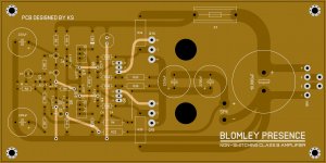
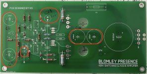
First, thanks for sharing the gerbers and schematic but I'm curious why the schematic you posted labels Q1 and Q8 ztx453 and ztx553 respectively yet also labels the pin order BCE when those parts are only available in CBE. Did you mean to label Q1 and Q8 the TTC / TTA and also what are you using for Q14 and Q15 (and why are the footprints so gigantic)?
While I'm here, I happen to have a +60V supply but how can I resist the beauty of that giant ripple rejection cap -- do you have a favorite bridge rectifier for BR1? Also, by my calculations a 44Vrms transformer? 125VA?
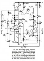
Some notes on construction. All small signal transistors are ztx453 / 553, except drives, they are Toshiba TTC / TTA 004B. If you want to use different transistors, check the pinouts. In the feedback network, increase the elko from 200uF to 470uF for proper bass response.
I hope I don't get in trouble for reviving this but surely I'm not the only one who will find this thread on google (and for the next 20 years, even).
First, thanks for sharing the gerbers and schematic but I'm curious why the schematic you posted labels Q1 and Q8 ztx453 and ztx553 respectively yet also labels the pin order BCE when those parts are only available in CBE. Did you mean to label Q1 and Q8 the TTC / TTA and also what are you using for Q14 and Q15 (and why are the footprints so gigantic)?
While I'm here, I happen to have a +60V supply but how can I resist the beauty of that giant ripple rejection cap -- do you have a favorite bridge rectifier for BR1? Also, by my calculations a 44Vrms transformer? 125VA?
Some notes on construction. All small signal transistors are ztx453 / 553, except drives, they are Toshiba TTC / TTA 004B. If you want to use different transistors, check the pinouts. In the feedback network, increase the elko from 200uF to 470uF for proper bass response.
I just ordered some of these PCB and wanted to say thanks, it saved me some work. May have spares available if anyone is interested, I ordered 10 boards since they were cheap compared to shipping from China. I'll be using these amplifiers as God intended, into a pair of 15 ohm Stentorians. 😀
Well I messed that up.
Its a bit subtle. Circuit noise is stochastic and cannot be removed by balancing the circuit and take the differential at the receiving end. In fact, it does increase circuit noise by 3dB with respect to a single ended channel.
What is does largely cancel is RF and other external noise radiated or induced into the lines, provided that both lines have the same source- and receiver impedance. That is the requirement for balanced line noise reduction: that both lines have the same impedance to ground.
Jan
I hope I don't get in trouble for reviving this but surely I'm not the only one who will find this thread on google (and for the next 20 years, even).
First, thanks for sharing the gerbers and schematic but I'm curious why the schematic you posted labels Q1 and Q8 ztx453 and ztx553 respectively yet also labels the pin order BCE when those parts are only available in CBE. Did you mean to label Q1 and Q8 the TTC / TTA and also what are you using for Q14 and Q15 (and why are the footprints so gigantic)?
While I'm here, I happen to have a +60V supply but how can I resist the beauty of that giant ripple rejection cap -- do you have a favorite bridge rectifier for BR1? Also, by my calculations a 44Vrms transformer? 125VA?
Sorry for the late reply. In positions Q1 and Q8, I designed TO-126 case transistors from the beginning, considering that 20mA is not enough for proper sound. (reason for this has already been discussed above) 60-80mA is optimal, so you need a larger transistor than ZTXs, optionally with a small heat sink. Therefore, the pinout is different. Q14/15 are NJW0281G/NJW0302G.
Bridge rectifier that I used: GBU25KH Diodes Incorporated | Mouser Hungary
In positions Q1 and Q8, I designed TO-126 case transistors from the beginning ...
Tr7 and Tr8 of your last post ?
He's alive! Wow this thread revival made my day! Thanks @egra and the others!
Do you have any suggestions for the Q1/Q8 TO-126? The TTA previously mentioned? Would the NTE184/NTE185 here be okay?
Update: I forgot to ask about transformer size if anyone has any tips.
Do you have any suggestions for the Q1/Q8 TO-126? The TTA previously mentioned? Would the NTE184/NTE185 here be okay?
Update: I forgot to ask about transformer size if anyone has any tips.
Last edited:
Do you have any suggestions for the Q1/Q8 TO-126? The TTA previously mentioned? Would the NTE184/NTE185 here be okay?
I'll be using BD139/BD140 but anything with a voltage rating over 40 volts should do.
I forgot to ask about transformer size if anyone has any tips.
Depends if you're going to use separate power supplies for each channel. It will require peak currents of 2A at full power into 8 ohms so a 120VA transformer per channel should do the job.
Requirements into 15 ohms are a lot lower. I'll be using a 24V 5A (120VA) transformer for both channels and voltage doubling it. You could also use switchmode supplies if you'd like it to weigh less.
Does anyone need Sprint Layout 6 files?
I use Eagle but I'll take a copy anyhow since this looks like a good program and I might buy it.
When Blomley says "to minimum" on diode side, does he mean to 0 ohm or to 500 ohm (on the diode side)? I built one but my idle current is fixed at 87.3mA no matter what I turn. I made a mistake somewhere. Building another now. I'm going to set them to what's in the spice settings before I solder them on this one. Also, just to be clear, quiescent current is measured between the collectors of Q14 and Q15 (Blomley's TR11 and TR12), right?
I have a few more questions if @egra or anyone else can help.
1) Do I have C6 and C9 labeled correctly and what is their recommended voltage?
2) The @egra PCB has 2 D4, one of which is not in the @egra schematic. It connects Q2's base to R10. This is D3 in Blomley's schematic and is also a 1N914?
3) Voltage for @egra C13 1uF 100V? This is Blomley's C6 (500uF?).
4) The @egra C10 is Blomley's C7 (2500uF) - also curious about recommended min voltage for these.
This is technically my second power amp build ever and the last was in 2003. Thank you for your patience with my very basic questions 😱
Attachments
- Home
- Amplifiers
- Solid State
- The Blomley Class B amplifier