Oh, I think I see. Red is connected to ground. That's how it's inverted.Hi Mooly, if I look at the ACA wiring I see no invertion. Red is plus on both sides. On inputs as well as on speaker terminals. Could you explain where the invertion happens? Thank you! View attachment 947353
Yes, so with the inverting Korg, you flip it at the output and two inversions = correct
absolute phase.
absolute phase.
I plan to use this Mean Well voltage converter to make +/- 12 volts from the 24 volt SMPS to power a muses volume control. Do I need any additional parts for this such as capacitors? Or is a simple straight in/out wiring set up acceptable?
Thanks for any info.
Thanks for any info.
Attachments
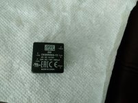
A datasheet exists at https://www.meanwell-web.com/content/files/pdfs/productPdfs/MW/DKMW06/SKMW06,DKMW06.pdf showing input EMI filtering to comply with the European EN 55032 requirements. It will be wise to follow these recommendations.
And the 10 uF output capacitor.
Best regards
And the 10 uF output capacitor.
Best regards
Last edited:
I plan to use this Mean Well voltage converter to make +/- 12 volts from the 24 volt SMPS to power a muses volume control. Do I need any additional parts for this such as capacitors? Or is a simple straight in/out wiring set up acceptable?
Thanks for any info.
I started to use one of these and then discovered the additional components needed. On the advice of someone on this list I switched to the Meanwell NSD10-D series and added a filter to the Korg pcb to isolate the Meanwell from the Korg. This filter is from another diyaudio thread here, and seems to work extremely well.
PO89ZB , an inline DC filter for SMPS wall warts . Preamps, HPA, Korg NuTube, etc
They now sell the SMPS filter PCB, plus a kit of all parts, in the diyAudio Store. At a bargain price too.
link to Store sales page
link to Store sales page
Thanks, that’s an awesome device, I bought four of them.
If I’m using the dc/dc converter to +/- 12 for the muses on this I’m unclear where in the line it goes. Will the one on the 24vdc smps take care of everything?
If I’m using the dc/dc converter to +/- 12 for the muses on this I’m unclear where in the line it goes. Will the one on the 24vdc smps take care of everything?
I've decided to buy another Korg B1 to use as a buffer between the head unit in my car and the DSP to make for some tube sound in my three way front plus subwoofer in the boot setup. I've sourced a 12volt DC to 24volt DC converter and I'll shock mount the B1 to help prevent microphonics. Photos' to follow.
Ground question
Hi
i have build the sigma 11 psu, to usage with korg preamp.
I have a ground question.
The amb.org site they say isolate the device from chassis,and one signal ground with 10k ohm and a 0,1uf cap, should i do this with b1 korg?
Quote
«If your chassis is metal, the AC earth ground connection on your IEC receptacle should be tied securely to the chassis. This is a safety measure, to prevent electric shock if any AC wiring comes loose. If the device being powered by the σ11 also resides in the same chassis, you should isolate the device's signal ground from the chassis (making sure that all input and output jacks are isolated). Then, connect the signal ground to the chassis through a "ground loop breaker". This prevents a potential ground loop which would cause hum and noise. A ground loop breaker is a 10Ω 5W resistor in parallel with a 0.1µF capacitor rated at more than 250VAC. For safety this capacitor should be rated for class X or Y with flame retardant casing. See the M³ amplifier wiring instructions for details.»
Andreas
Hi
i have build the sigma 11 psu, to usage with korg preamp.
I have a ground question.
The amb.org site they say isolate the device from chassis,and one signal ground with 10k ohm and a 0,1uf cap, should i do this with b1 korg?
Yes. 10Ω resistor, not 10kΩ. Another way is to use CL-60 thermistor or 35A rectifier bridge.
Last edited:
Re:Ground Loop breakers.
qwertyl is right. Make sure it's a 10 ohm resistor as Ti Kan/AMB recommends.
The other way is the CL-60 thermistor many use here.
And Andrew Russell/Bonsai of Hifisonix has a new tutorial where he recommends 35A rectifier bridges (which are great for GROUND FAULTS, not just ground loop breaking).
The pdf is here:
Wiring Up Dual Mono Amplifier
Best,
Anand.
I've decided to buy another Korg B1 to use as a buffer between the head unit in my car and the DSP to make for some tube sound in my three way front plus subwoofer in the boot setup. I've sourced a 12volt DC to 24volt DC converter and I'll shock mount the B1 to help prevent microphonics. Photos' to follow.
Have you considered this all-FET alternative? Might be better for use in a shock-prone moving vehicle.
https://www.firstwatt.com/pdf/art_h2_v1.pdf
My add-on board for the Korg B1 is taking shape. I've kept it the same width dimension as the Korg board and, by moving the Korg pcb one inch toward the front panel, there's plenty of room between the original pcb and the back panel connectors for the new board.
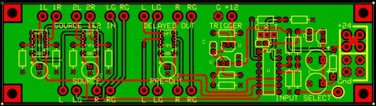
The features:
Inputs switched right at the back panel via relays controlled by the front panel toggle.
Output relay delays output by x seconds (TBD), and instantly (in about 5~10 milliseconds) disconnects the output when power is lost, so no more loud noises at turn-on, turn-off or power failure.
Trigger circuit activates power amp when preamp is turned on, so you have full control from the front panel on/off toggle switch.
Added location to consolidate all of the various connections to +24V.
Attachments
Last edited:
Many, including I, prefer switching the grounds as well as signal for each input. This reduces some instances of ground loops (depending upon the internal grounding scheme of the connected input sources. Switched grounds - for me - are also simpler to conceptualize: only one signal and ground is connected to the main circuitry (volume pot/attenuator/preamp/buffer) at any given time.
However, I want to emphasize this is a preference, and is not a comment or criticism of your scheme which is also completely acceptable and typically used in commercial products.
However, I want to emphasize this is a preference, and is not a comment or criticism of your scheme which is also completely acceptable and typically used in commercial products.
Many, including I, prefer switching the grounds as well as signal for each input. This reduces some instances of ground loops (depending upon the internal grounding scheme of the connected input sources. Switched grounds - for me - are also simpler to conceptualize: only one signal and ground is connected to the main circuitry (volume pot/attenuator/preamp/buffer) at any given time.
However, I want to emphasize this is a preference, and is not a comment or criticism of your scheme which is also completely acceptable and typically used in commercial products.
I am matching the original scheme as it exists in the diyaudio B1K kit.
Have you considered this all-FET alternative? Might be better for use in a shock-prone moving vehicle.
https://www.firstwatt.com/pdf/art_h2_v1.pdf
It crossed my mind but it's the tube sound I am looking for in my car. If it doesn't work out I'll give the Korg B1 to a friend.
It crossed my mind but it's the tube sound I am looking for in my car. If it doesn't work out I'll give the Korg B1 to a friend.
The H2 IS a tube without the tube. I think it's what you want. Also, much smaller, so good for a vehicle.
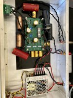
Just finished my B1 build!!
It's certainly not the cleanest example (frankenstined it a bit with some vintage caps) but with the help of my 3 year old we got it done within a few weeks - slow and steady.
I suspended the entire board on sorbothane and put sorbothane washers under the PCB, under the nutube, and under the case itself where the through bolts go through. Currently the preamp sits on my desk where I routinely type like a 500 pound gorilla and I'm not getting any microphonics. Have to hit the case with a piece of metal fairly sharply to get the tube to ring so I must have gotten a fairly good one or my suspension is working better than anticipated!
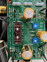
Voltages are as follows -
T1 - 24v
T2 - 23.19v
T3 - 22.38v
T4 - 8.86v
T5 - .632v
T6 - .649v
T7 - 9.54v
T8 - 9.53v
Have to say the sound is very surprising - especially as I wasn't sure what to expect. Dynamic, punchy, great tonality, and very holographic - really really enjoying the sound. Thanks to all 648 pages of this thread I was able to avoid any errors and it fired up the first time without any issues. A special thanks to Mr. Nelson for putting this together, was a great experience and one that I was able to pass on to my son (he's already asking what 'Papas' next project will be). I'd also like to thank Claude for his detailed analysis, I've used his capacitor guidance for my own build (.22mF up front, 1mF in the middle, and 3mF for the output).
Had a ton of fun putting this together, hope you like the end result as much as I do - really is a pleasure to listen to 🙂
It's certainly not the cleanest example (frankenstined it a bit with some vintage caps) but with the help of my 3 year old we got it done within a few weeks - slow and steady.
I suspended the entire board on sorbothane and put sorbothane washers under the PCB, under the nutube, and under the case itself where the through bolts go through. Currently the preamp sits on my desk where I routinely type like a 500 pound gorilla and I'm not getting any microphonics. Have to hit the case with a piece of metal fairly sharply to get the tube to ring so I must have gotten a fairly good one or my suspension is working better than anticipated!
Voltages are as follows -
T1 - 24v
T2 - 23.19v
T3 - 22.38v
T4 - 8.86v
T5 - .632v
T6 - .649v
T7 - 9.54v
T8 - 9.53v
Have to say the sound is very surprising - especially as I wasn't sure what to expect. Dynamic, punchy, great tonality, and very holographic - really really enjoying the sound. Thanks to all 648 pages of this thread I was able to avoid any errors and it fired up the first time without any issues. A special thanks to Mr. Nelson for putting this together, was a great experience and one that I was able to pass on to my son (he's already asking what 'Papas' next project will be). I'd also like to thank Claude for his detailed analysis, I've used his capacitor guidance for my own build (.22mF up front, 1mF in the middle, and 3mF for the output).
Had a ton of fun putting this together, hope you like the end result as much as I do - really is a pleasure to listen to 🙂
Attachments
- Home
- Amplifiers
- Pass Labs
- B1 with Korg Triode