FWIW, I replaced the nuTube in my stricken B1 and all is again right with the world.
My new F6 sounds even more angelic with the B1 in front.
Thanks for the pointers.
My new F6 sounds even more angelic with the B1 in front.
Thanks for the pointers.
I fire it up my prototype this morning (B1 Nutube in wood case) plug in the main input of a restored Marantz 2275 with Mission 753 with upgraded crossover.
I will have to deal with microphonics, but from what I hear, with the two bias potentiometers untouch, it is like hearing a cross beetween the best of both world. Wonderfull transparency and definition with a warm presentation.
I will have to deal with microphonics, but from what I hear, with the two bias potentiometers untouch, it is like hearing a cross beetween the best of both world. Wonderfull transparency and definition with a warm presentation.
here is the complete board.
Hi, how do you like the ODAMs?
I have ordred 0,47uf / 1,0uf / 2,2uf for my B1K.
How do you solder in the ODAMs ? Regard to outer cap on capacitor.
Fank
Has anyone experienced “digital” noise from their pre-amp? I am running a pair of ACAs in mono, with the B1 connected and powered but with no input signal, I can hear faint noise at my speakers, kind of like some digital modulation ( think of old GSM) but random in nature. If I turn the pre-amp off, the noise goes. Are these known for picking up noise? Any threads or links?
I get this whether running SMPS or Linear 24v supply.
Thanks, Jon
Ok, so if anyone else get a similar “digital chatter” coming through your B1, check if your WiFi router is in close proximity. Whilst investigating my noise issue I noted that if I place my hand near the lid the noise dropped. I then moved my router antenna to a vertical position the noise went away.
Next to change the B1 wiring to separate the channels.
Does anyone invert the output of their B1? Does the Triode phase invert the input signal? If so, would swapping GND and Sigout work?
You may want to read Nelson's paper again: (nearly) all about absolute phase, inversion and so called negative phase harmonic and how to play or wire the B1K is covered inside. Many options depending on what you like best or want to achieve...
Happy reading
Claude
Happy reading
Claude
Ok, so if anyone else get a similar “digital chatter” coming through your B1, check if your WiFi router is in close proximity. Whilst investigating my noise issue I noted that if I place my hand near the lid the noise dropped. I then moved my router antenna to a vertical position the noise went away.
Next to change the B1 wiring to separate the channels.
Does anyone invert the output of their B1? Does the Triode phase invert the input signal? If so, would swapping GND and Sigout work?
I too got confused about al this phase inversion stuff, as I use my B1K as input to an ACA, which itself is phase inverting, but which is wired in the standard wiring diagram to invert the phase of the speaker terminals thus correcting the phase inversion of the ACA itself. So as an experiment I inverted the speaker phase of an ACA with a B1K upstream of it and it was awful, soundstage collapsed completely, like I was listening in mono.
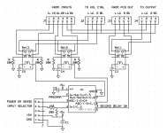
I have it in mind to install some additional circuitry in my Korg B1. First, I am indeed suffering from the turn-on and turn-off thumps and when my new subwoofer arrives I'm guessing it's going to get a lot louder.
I thought I'd move the Korg pcb about one inch or more toward the front panel to give myself room between the main board and the rear input/output sockets.
Note that the relays are of the hermetically-sealed, latching variety which consume no current and generate no magnetic field when in the steady-state regardless of which position it is in. Switching is accomplished by charging or discharging a capacitor through the relay coil. No diode is required and the resistance of the relay coil acts to limit current so no resistor is needed so long as the current demand does not exceed the ability of the chip to deliver. Relay coil voltage does not collapse to cause damage -- it gradually dissipates as the capacitor charges or discharges.
Disregard the logic chip circuit -- it's a partial circuit and I may go to a 14-pin chip to accommodate other capabilities if the need arises or to insure relay operation by tying two pins together to double the current delivery capability when switching.
I have a number of goals:
1) Make my input switching noise go away by moving the actual switching onto relays located right at the input sockets and by always grounding the input not in use to ground through a 20K (?) resistor. The front panel switch then uses a single wire to control the input relays which do the actual switching.
2) Make the power on/off thump a non-issue by inserting a relay with a 4-second turn on delay and instantaneous turn off when power is removed.
3) Install a 12vdc 25mA trigger circuit to control the downstream power amplifier.
I would like to hear any suggestions and advice that might make my design better before I start drawing a pcb layout. If I have missed a desirable feature that might fit here, I'd like to hear about that, too.
Questions I have:
1. Is 20K a good grounding resistor value for the input that is not being listened to?
2. Would the output relay circuit benefit from handling like the input relays -- a 20K or other value resistor terminating the output cable to ground when the output relay has disconnected the Korg from the cable?
3. Is there any benefit in provisioning a manual output relay control, or is the power-monitoring of the output the only useful control?
4. Is 12vdc @ 25mA enough current to properly drive a trigger circuit? Should I plan on different values of current?
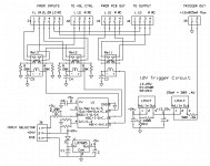
Attachments
Last edited:
I'm confused too. I assume you should connect the white speaker cable connector to the red amp output and the red to the white of BOTH speakers.I too got confused about al this phase inversion stuff, as I use my B1K as input to an ACA, which itself is phase inverting, but which is wired in the standard wiring diagram to invert the phase of the speaker terminals thus correcting the phase inversion of the ACA itself. So as an experiment I inverted the speaker phase of an ACA with a B1K upstream of it and it was awful, soundstage collapsed completely, like I was listening in mono.
I got Here 3 quads of matched 2sk170.. But cant get another quad to Do a balanced preamp... Can I use lsk170 there too? Or will they Sound different?
I'm confused too. I assume you should connect the white speaker cable connector to the red amp output and the red to the white of BOTH speakers.
That is the condition that destroyed the sense of soundstage in my system. I wire my ACA v1.8 per it's diagram (reversed output polarity) and the speakers red-to-red and black-to-black and it sounds great.
I've tried searching the thread for this question, but the search function never returns....so....
I've got a Meanwell SMPS that I'll use with this (with Mark's SMPS filter). But I was thinking I might also try a regulated supply. The VRDN supply only goes up to 20V (and is bipolar, which we don't need here). What good unipolar regulated supplies have people used?
It would be great, come to think of it, if the store carried such a thing. It seems a pretty common need.
Matched quads of 2SK170 will be in the store before long. The LSK170's run fine,
but sufferers of audio nervosa will have to wait a littlebit.
but sufferers of audio nervosa will have to wait a littlebit.
So this means that the phase invertion is Already solved within the ACA if you follow the build instructions correctly?That is the condition that destroyed the sense of soundstage in my system. I wire my ACA v1.8 per it's diagram (reversed output polarity) and the speakers red-to-red and black-to-black and it sounds great.
The ACA is an inverting amplifier, you can not change that aspect of the design.
You as the user can preserve correct phase by reversing the speaker connections, something the ACA does if built according to the instructions by swapping the Red and Black terminals over.
You as the user can preserve correct phase by reversing the speaker connections, something the ACA does if built according to the instructions by swapping the Red and Black terminals over.
Anyone built one of these for each channnel? In effect providing balance and control of troubleshooting if needed. I’m experiencing some inbalance in right and left channels for some reason with the one I built as instructed in the guide.
I built a Salas UltraBiB for use with my B1K. It sounds a bit more crisp and clean compared to the the SMPS. I didn't bypass any of the filtering on the B1K, which might be a worthwhile experiment.
I've tried searching the thread for this question, but the search function never returns....so....
I've got a Meanwell SMPS that I'll use with this (with Mark's SMPS filter). But I was thinking I might also try a regulated supply. The VRDN supply only goes up to 20V (and is bipolar, which we don't need here). What good unipolar regulated supplies have people used?
It would be great, come to think of it, if the store carried such a thing. It seems a pretty common need.
Hi Mooly, if I look at the ACA wiring I see no invertion. Red is plus on both sides. On inputs as well as on speaker terminals. Could you explain where the invertion happens? Thank you!The ACA is an inverting amplifier, you can not change that aspect of the design.
You as the user can preserve correct phase by reversing the speaker connections, something the ACA does if built according to the instructions by swapping the Red and Black terminals over.

- Home
- Amplifiers
- Pass Labs
- B1 with Korg Triode