Yes I have try only electrochemicals Simic II and Nichicon then only polypro ( big size )
Mixture of electrochemicals bypassed with small size ~ 2uF pp sound fantastic
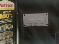
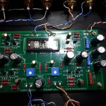
here is the complete board.
What does your power supply look like? Heater PSU is separate? I see two power entries plus a ground for the PSU. I am assuming one is for the heaters?
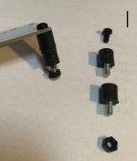
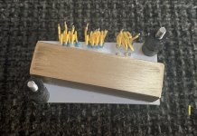
this is my solution for damping the nutube.
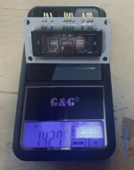
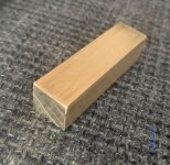
under the stand off board is a piece of brass
for more mass (120g)
Please keep the forum advised of your experience in using these sockets!
Such a beautifulB1K
Waiting for music quality descriptions 😀 Congratulations
Edit: what is volume potentiometers ?

thank you 🙂
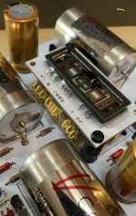
volume is no potentiometer,
here i use my own muses boards.
Please keep the forum advised of your experience in using these sockets!
Here again some photos to explain.
the stand off board with the nutube weighs only 14g.
this is not enough, is stimulated so very quickly to vibrate,
also the dampers need a certain load to work properly.
I have bent the connecting wires like springs, so that they allow movement,
but also contribute to damping.
I’ve tested it, and it works fine.
a lot of effort and work, but it’s worth it.
Attachments
Construction Error occured
I just finished my board and the kit, checking all resistors, PCU etc. before soldering the rest.
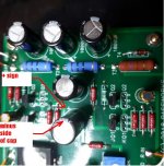
Then I connected the Nutube B1 to the 24V supply. The left blue troide was slimming strongly, the right not that much. T1 was measured with 24V, T3 only with around 20.5 (should be around 23V) and T4 with 9V. After a few seconds, the right 1000uF Elko of the right channel had an issue.
Does anybody knows what's the problem?
Thanks a lot
Karim
I just finished my board and the kit, checking all resistors, PCU etc. before soldering the rest.
Then I connected the Nutube B1 to the 24V supply. The left blue troide was slimming strongly, the right not that much. T1 was measured with 24V, T3 only with around 20.5 (should be around 23V) and T4 with 9V. After a few seconds, the right 1000uF Elko of the right channel had an issue.
Does anybody knows what's the problem?
Thanks a lot
Karim
Are you able to post some photos of your board so others can see if there are any build errors made?
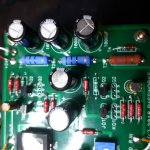
In the picture 20210410_201003.jpg one of the big electrolytics appears to be installed with polarity reversed, minus side of the cap near a + sign.
Hi.
You that have change the electrolyts in signal ( the six 10uF ) to polyproplyne.
Was it worth it?
And what value did you use, input-mid-output ?
Bypass them or not?
Frank
You that have change the electrolyts in signal ( the six 10uF ) to polyproplyne.
Was it worth it?
And what value did you use, input-mid-output ?
Bypass them or not?
Frank
Hallo Karim,
it looks like you put the two 1000 uF capacitors in the right channel in backwards, as well as the right 10 uF capacitor ... 😱
have a look where the "+" sign is in the silkscreen of the board.
Best regards,
Claas
Edit: loudthud was quicker ... 🙂
Edit Edit: when you change the capacitors, also have a look at the resistors connected to them. Reversed capacitors can draw large currents, that could overheat the resistors as well. (don't have the schematic ready as for the resistor numbers)
Last edited:
Attached you can find some pictures. T5 an T6 were also 0.6 VDC.
Thanks a lot Karim
In the picture 20210410_201003.jpg one of the big electrolytics appears to be installed with polarity reversed, minus side of the cap near a + sign.
+1... Nice eyes Loudthud. You beat me to it. Just for clarity re: which one.
Edited to add and update the pic to grab the other two that Chede caught. 😀 What an awesome place.

Last edited:
Thanks a lot to you all guys. Yes, all three capacitors (2x 1000uF and 1x 10uF) have wrong polarities. Soldering to late in the evening yesterdays make these failures.
1. I will change the capacitors --> buying new ones --> do you have better recommendations (tubning options)?
2.I will check the resistors as well.
Thanks a lot
Karim
1. I will change the capacitors --> buying new ones --> do you have better recommendations (tubning options)?
2.I will check the resistors as well.
Thanks a lot
Karim
it's handy for final/later check
at least I'm finding it useful, no need to look at printed parts-placement paper/pic
at least I'm finding it useful, no need to look at printed parts-placement paper/pic
To second Loudthud... make that even 2!
The 2 big lytic caps, left pair on your first picture, seem mounted thew rong way!
Claude
EDIT: sorry, posted/replied when I read your post on my phone, in the meantime many others did already reply far better... anyway, you know what's wrong
The 2 big lytic caps, left pair on your first picture, seem mounted thew rong way!
Claude
EDIT: sorry, posted/replied when I read your post on my phone, in the meantime many others did already reply far better... anyway, you know what's wrong
Last edited:
I have just ordered the B1 buffer kit from passdiy.com with a view to using it to follow my LDR volume control.
I note that the original Pass design uses paired FETs with no resistor in the Q2 circuit, whereas the Korg B1 does use a resistor to match FETs. Can someone explain to me why this has come about? What is the advantage of the latter circuit? Is there an advantage that affects operation of the circuit, or is it simply ease of matching?
I note that the original Pass design uses paired FETs with no resistor in the Q2 circuit, whereas the Korg B1 does use a resistor to match FETs. Can someone explain to me why this has come about? What is the advantage of the latter circuit? Is there an advantage that affects operation of the circuit, or is it simply ease of matching?
Last edited:
The original circuit used Toshiba JFET's which are now rare and expensive, even the ones from the DIYAUDIO store are expensive. Nelson used JFET's which are available and not obsolete.
6L6 posted he could hear no difference between the different JFET's.
6L6 posted he could hear no difference between the different JFET's.
The good news is that between Linear Systems and purchases of some Toshibas
the supply situation is improving.
That said, the B1Korg is not a circuit that focuses on the lowest possible distortion.

the supply situation is improving.
That said, the B1Korg is not a circuit that focuses on the lowest possible distortion.
Soldering to late in the evening yesterdays make these failures.
Karim,
I think we all have done the same thing. Building late into the hight. I know that I have and made mistakes because I should have put the soldering iron down. Actually, I have even made cocktail mistakes.
Just last night I was working late on my F2J and almost wired one of the power supplies backward. Lucky I caught it before powering it up.
Yeah, that's how I came up with my recommendation to check the resistors as well.
A few weeks ago, I put a local buffer capacitor in backwards on the power amp board of a Tandberg TR 1040 I was restoring. I noticed it because the voltage dropping resistor before it just burned away when switching the receiver on. 😱
Luckily, no other damage than the resistor and cap ... 🙂
Regards, Claas
- Home
- Amplifiers
- Pass Labs
- B1 with Korg Triode